

Embedded Raspberry Pi Compute Module IOT Board---The Excellent PCB projects of this week

SUMMARY?
You can pair the Compute Module capabilities with this carrier board to offer the exact hardware and final package that you need for your custom application having the flexibility of using the raspberry pi in a more diverse form factor of your choice.
Video shows the boot-up test where the transistor enables boot-up from the eMMC flash indicated by the LED turning off at the edge. The red LED that lights up when Ethernet connection is made at the end of the video is an indication of half-duplex (Data packets are sent back and forth), which is a feature in the LAN chip, help to see whether communication is been initiated or not and in which mode, FULL DUPLEX or HALF DUPLEX.
DESCRIBTION OF PROJECT?
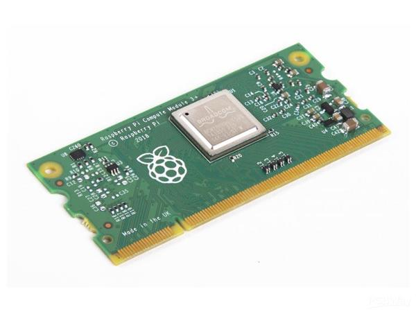
If you have not heard of the Raspberry Pi Compute Module, it’s basically a Linux computer with the form factor of a laptop RAM stick.
The on-board eMMC also eliminates the need for an external micro SD card, which makes the Compute Module perfect for designing Raspberry Pi based products and more.
The Compute Module is designed for use in custom devices where capabilities of the Pi are desired but do not meet unique form factor or I/O requirements. The Compute Module is a Raspberry Pi that has been shrunk down to fit on a smaller form factor with two high-speed, high-density 100-pin mezzanine connectors.
The Raspberry Pi Compute Module is derived from the CM3 board but offers better thermal behaviour under load. That’s possible because of the Broadcom’s 64-bit BCM2837B0 application processor, which was also used in last year’s Raspberry Pi 3B+, and 1GB of LPDDR2 RAM. The CM3+ draws heat away from the processor faster than the CM3 and is rated to support temperatures between -20°C and 70°C (-4°F and 158°F).
You can then pair the compute capabilities with a carrier board of your choice to offer the exact hardware and final package that you need for your custom application.
✌️✌️✌️✌️✌️✌️
With this in mind, the compute module is primarily designed for those who are going to create their own PCB.
So here we are with this new design to allow the use of the fantastic BCM chip on the CM.

The compute module on sale, appears to be lacking in terms of popularity compared to the traditional Raspberry Pi Model A and B. As a result, there aren’t many open source hardware projects out there based on it. Trying to design you own board, you will notice limited resources available to you.
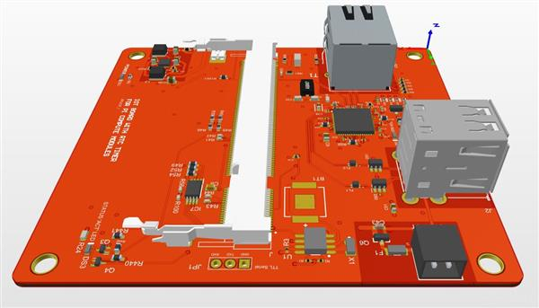
Creating your own PCB allows you the flexibility to add components that you need and also get rid of any you do not need to save yourself money. This PCB makes use of the fantastic LAN9512 USB-to-Ethernet chip.
This is a 4 layered PCB board that I designed, used, and it works perfectly with no issues at all, and if you need HDMI connection, you can add it much easier to allow displays to be connected depending on your project. You will get this sleek PCB with 4mm mounting holes for your project (Photo below) newest version and the design files for editing if you wish to add few other parts, I used Altium software, which should be easy to convert to other software like eagle etc., for editing.
?♀️?♀️?♀️?♀️?♀️
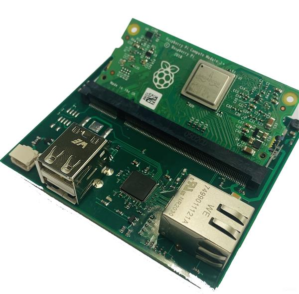
I ordered the first designed version shown in the photos (below) and it was perfectly made and works great (5 PCB sample cost $115 assembled), test shows all USB and Ethernet port works great and I build some cool IOT projects with it. The second edited module (Data packs attached) gives users the mounting holes for easy mount for your project.
COMPUTE MODULE 3+
?♀️First Version I designed below and used for the test, with results shown below.
The compute module I used has the 16GB eMMC flash device which is the equivalent of SD card in raspberry pi integrated on it, great and very reliable.
What can you do with this? am glad you asked. This allows users to use the raspberry pi core in a more flexible form factor, can be use in custom devices where capabilities of the pi are desired but do not meet the unique form factor.
LAN CHIP CONNECTION TEST?

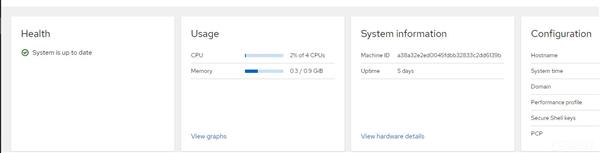
OPERATION TEST RESULTS?

ADVANTAGES✍️✍️✍️
> It provides 10/100Base-T ethernet connectivity to the compute module
> On-board eMMC flash device to upload your image to
> RTC timer to keep up accurate date and time
> Easy programmable CM3 to use on the module
SPECIFICATION✍️✍️✍️
- SoC: Broadcom BCM2837B0, Cortex-A53 (ARMv8) 64-bit SoC @ 1.2GHz
- Memory: 1GB LPDDR2 SDRAM
- 8GB/16GB/32GB eMMC Flash memory
- RJ45 Ethernet connectivity
- Onboard Gigabit Ethernet PHY supporting IEEE1588
- 2 × USB 2.0 interface
- PCIe Gen 2 x1 interface
- 28 GPIO signals
- Dual-display support at resolutions up to 4K, video decode at up to 4Kp60
- Multimedia supports H.265 (4Kp60 decode); H.264 (1080p60 decode, 1080p30 encode); OpenGL ES 3.0 graphics
Well, what the Compute Module is able to achieve is largely bound by the carrier board that you pair it with! With the right carrier board, you’ll have virtually limitless possibilities thanks to the module’s flexibility. My carrier board provides me with remote access to my connected devices all around the world, you can edit the carrier board to suit you need.
Microchip LAN9512 Details✍️✍️✍️
The LAN9512 and LAN9514 are fully-integrated, hi-speed USB 2.0 hub and high-performance 10 / 100 Ethernet controllers. They are specifically designed to provide system architects with a low-cost, power-efficient, small-footprint USB to Ethernet and multi-port USB connectivity solution in a single package. SMSC’s LAN9512 / 9514 contain a hi-speed USB 2.0 hub with two (LAN9512) or four (LAN9514) fully-integrated downstream USB 2.0 PHYs, an integrated upstream USB 2.0 PHY, a 10 / 100 Ethernet MAC / PHY controller, and an EEPROM controller. The LAN9512 / 9514 simplifies system design by leveraging the existing USB stack, reducing PCB footprint by up to 65% compared to discrete competitive solutions.
The external EEPROM is optional depending on your use need, the chip works fine with or without the external EEPROM.
FEATURES✍️✍️✍️
- NetDetach low-power technology allows reduction of system power up to 25% by enabling the host CPU to enter a low-power state when the Ethernet connection is inactive.
- Built-in ± 8 kV / 15 kV contact/air discharge ESD protection on both USB and Ethernet PHYs
- UniClock technology simplifies the clocking scheme and reduces system BOM cost by using a single 25 MHz crystal for both USB and Ethernet connectivity - without the need for extra components when adding USB hubs
- Fully-integrated 2/4-port hi-speed USB 2.0 hub and 10 / 100 Ethernet controllers
THIS CAN BE UPGRADED TO ACCOMMODATE ANY PART YOU NEED WHICH MAY INCLUDE, HDMI, DISPLAY FFC CONNECTOR, FTDI ETC.
Enjoy a happy IOT project build.
If you have any questions hit me up here,adios!!!!
Comments
If you have any PCB board design requirements, you can visit here: