

Automatic Plant Watering System Using a Micro:bit---Micro:bit project sharing

Recently I saw a very interesting share from thediylife, Original shared link:https://www.instructables.com/Automatic-Plant-Watering-System-Using-a-Microbit/??????
The Micro:bit uses a moisture sensor to monitor the moisture level in the plant's soil and then switches on a small pump to water the plant if the soil gets too dry. This way, your plant is always looked after, even when you've forgotten about it or you're away.
✍️Supplies
- MicroBit – Buy Here
- Capacitive Moisture Sensor – Buy Here
- DC Pump – Buy Here
- Relay Module – Buy Here
- Ribbon Cable – Buy Here
- Storage Containers (Not the same, but should work) – Buy Here
- Power Supply – Buy Here
- M3 Screws – Buy Here
I’ve used the MicroBit version 2, but this project can be made using the first version as well.
Step 1: Preparing Your Components✍️
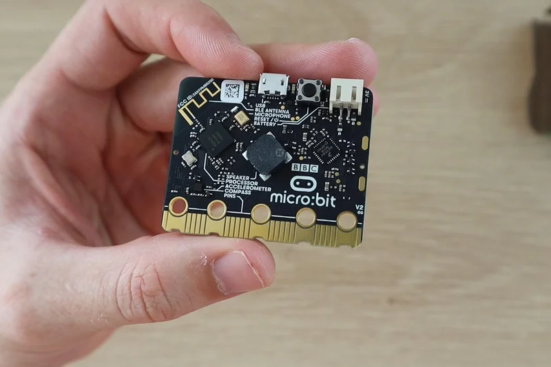
MicroBit is a small programmable micro-controller that has a number of onboard sensors and buttons, making getting started with programming really easy.
You can use block coding for children and less experienced programmers and JavaScript or Python for those who are more experienced with programming and want to get more functionality out of it. It also has a range of IO pins available for sensors and devices along it’s bottom edge.
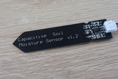
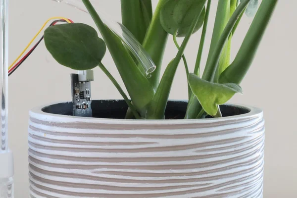
The capacitive moisture sensor I’m using runs on 3.3V, which is perfect to be used directly with the MicroBit.
Note: These capacitive sensors generally state that they operate between 3.3V and 5V, and output a maximum of 3.3V as they have an onboard voltage regulator. I've found that a lot of the cheaper versions of these sensors don't actually work with an input voltage of 3.3V, but require 3.5-4V before they actually "switch on". You'll need to be careful with this as the Micro:bit is only designed for an input voltage of up to 3.3V.
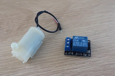
The pump will need to be turned on and off using a relay module. The relay module switches power to the pump so that the current isn’t flowing through the MicroBit.
Step 2: Designing the Circuit & Code in TinkerCAD✍️
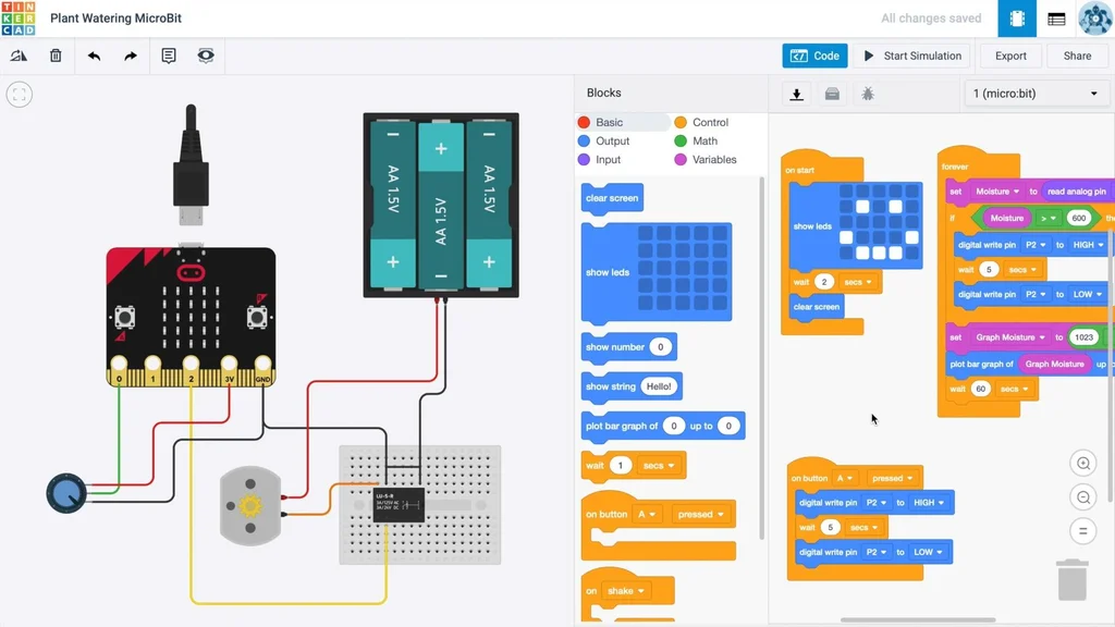
I designed the circuit and did the block coding in TinkerCAD since they’ve recently added the MicroBit to their platform. Block coding is a really easy way to build basic programs by just dragging and dropping function blocks.
I used a DC motor to represent the pump and a potentiometer to simulate the moisture sensor input as it also requires the same three connections.
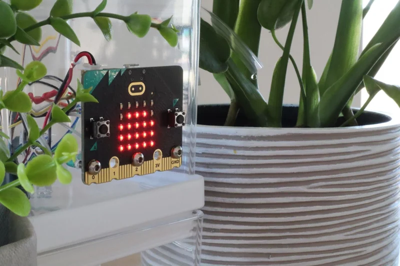
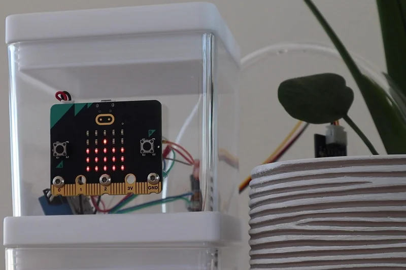
In my final version of the block code, the Micro:bit shows a smiley face when it’s turned on then starts taking moisture readings every 5 seconds and plotting them on the graph on the display. It also checks whether the moisture level is below the set limit, and if it is then it turns on the pump for 3 seconds. It continues to cycle the pump, with a 5-second break between cycles, until the moisture level is again above the limit.
I also added functions to the two buttons where button A turns the pump on for 3 seconds to manually water the plant, and button B shows the moisture level reading on the display.
Step 3: Testing the Circuit and Code✍️
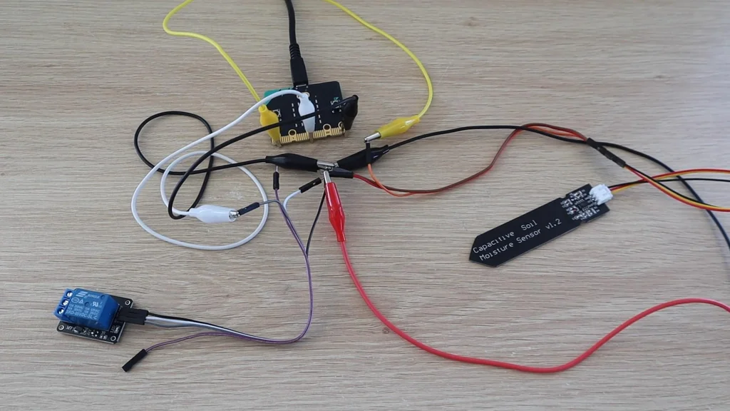
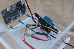
Once I was happy with the simulation running in TinkerCAD, I connected the components together on my desk to check that they worked in the same way. I made temporary connections using some jumpers and alligator clips to attach to the Micro:bit pins.
This was mainly to test that the Micro:bit was reading the correct values from the sensor and that the relay was able to be turned on and off.
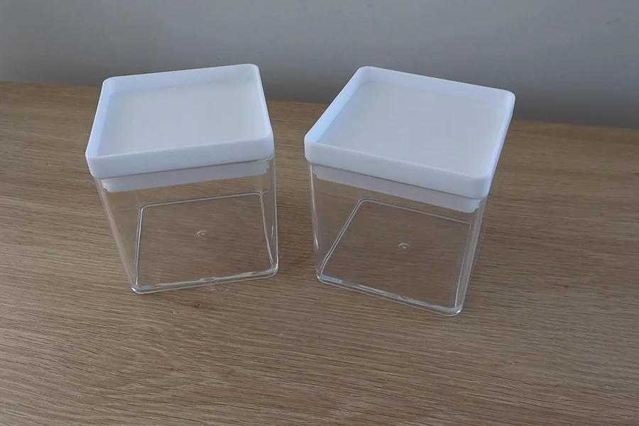
Step 4: Making the Water Tank✍️
Once I was happy with the test setup, I got to work on making a water tank, building the components into a housing, and doing the permanent electrical connections.
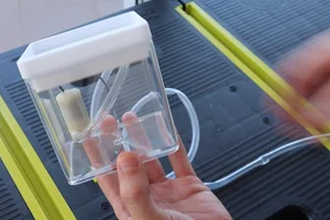
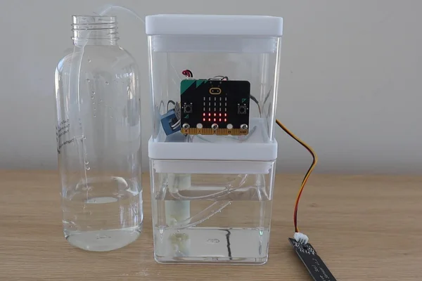
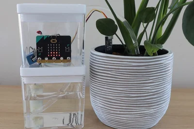
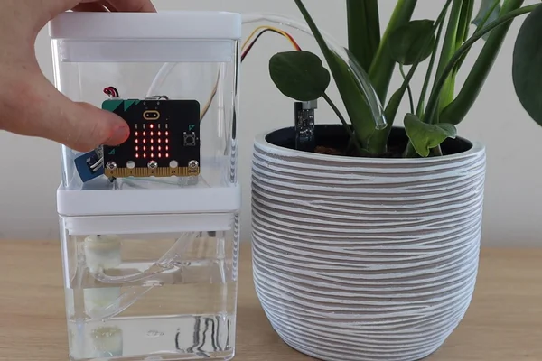
I found these two containers in a local discount store. They stack together so that I could use the bottom one as a tank and the top one to house the electronics.
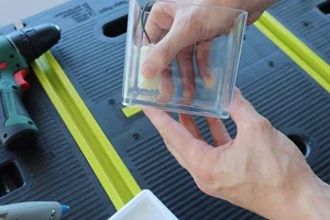
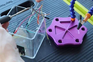
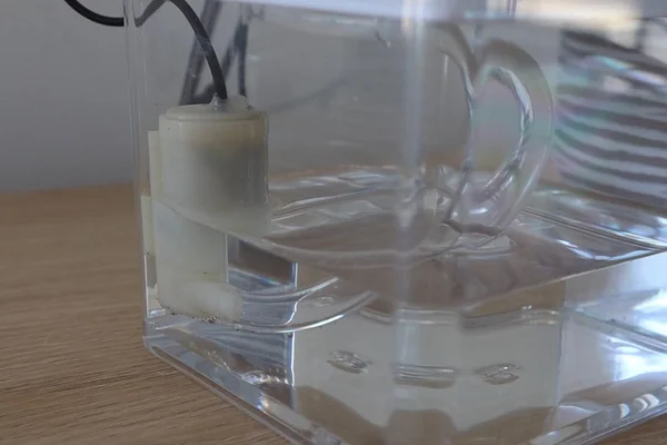
To make the tank, I needed to mount the pump into the tank with the water inlet as close to the bottom as possible, while still leaving enough room for the water to flow. I glued the pump in place using a glue gun.
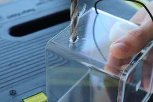
I then drilled holes for the wires to the motor and the tube for the water outlet.
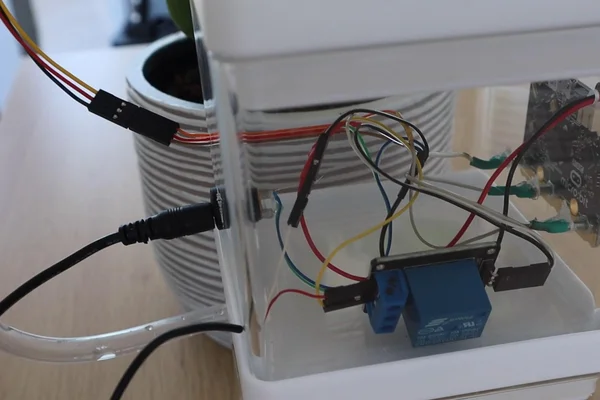
Step 5: Assemble the Electronics✍️
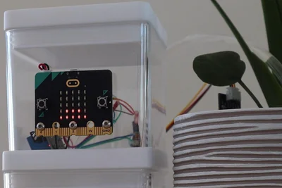
I wanted the MicroBit to be mounted onto the front of the housing so that it was easy to see, as I’m using the LED display on the front as a graph of the water level.
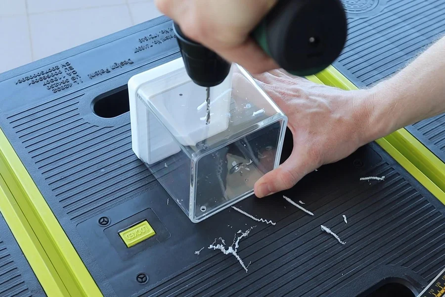
I drilled some holes through the front to hold the MicroBit and act as the connections to the IO pins on the bottom. I used some long M3 x 20mm button head screws to screw into the terminals on the IO pins and connect to the wiring on the inside of the case. I connected the wiring to the screws by wrapping some of the exposed wiring around the screws and then using heat shrink tubing to hold it in place.
I also drilled holes for the power lead to the Micro:bit, for the power socket at the back and for the pump and moisture sensor wires.
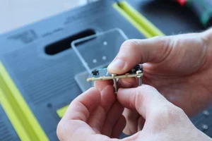
I then connected all of the wiring, soldering the joints, and connected the components together inside the housing.
Step 6: Testing the Watering System✍️
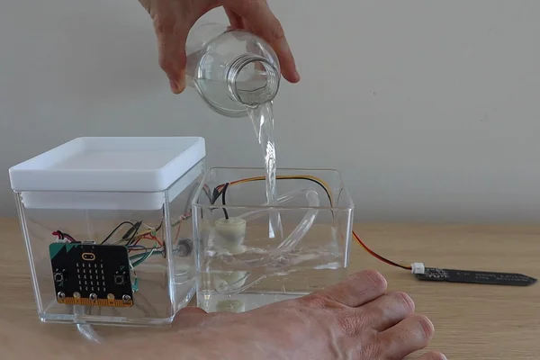
Now that all of the components are assembled, it's time for a bench test.
Comments
Have you built anything using a Micro:bit? Let me know in the comments section!
Awesome job, some great detail there!
I ended up doing a similar project with some inspiration from here.
https://www.youtube.com/watch?v=Kt17GFAu-D8
Awesome work! I used this for some inspiration to build my own automatic watering!
Some great detail, keep it up!