

ESP32 HMI Demo Code Updated - compatible with new version of esp32 package

When we first edited the demo code, we based it on the 2.0.3 version of the esp32 package, which resulted in compilation errors for many users who installed the new version of esp32. To solve this problem, we updated the esp32 demo code. The updated content is as follows:
For 5-inch esp32 screen:
1/2/2024 Updated:
The latest demo code for 5-inch screen also use LovyanGFX library. If you change the library from Arduino_GFX to LovyanGFX, the "->" need to be replaced into "."
#include <LovyanGFX.hpp>
#include <lgfx/v1/platforms/esp32s3/Panel_RGB.hpp>
#include <lgfx/v1/platforms/esp32s3/Bus_RGB.hpp>
class LGFX : public lgfx::LGFX_Device
{
public:


  lgfx::Bus_RGB     _bus_instance;
  lgfx::Panel_RGB   _panel_instance;


  LGFX(void)
  {


    {
      auto cfg = _bus_instance.config();
      cfg.panel = &_panel_instance;

      cfg.pin_d0  = GPIO_NUM_8; // B0
      cfg.pin_d1  = GPIO_NUM_3;  // B1
      cfg.pin_d2  = GPIO_NUM_46;  // B2
      cfg.pin_d3  = GPIO_NUM_9;  // B3
      cfg.pin_d4  = GPIO_NUM_1;  // B4

      cfg.pin_d5  = GPIO_NUM_5;  // G0
      cfg.pin_d6  = GPIO_NUM_6; // G1
      cfg.pin_d7  = GPIO_NUM_7;  // G2
      cfg.pin_d8  = GPIO_NUM_15;  // G3
      cfg.pin_d9  = GPIO_NUM_16; // G4
      cfg.pin_d10 = GPIO_NUM_4;  // G5

      cfg.pin_d11 = GPIO_NUM_45; // R0
      cfg.pin_d12 = GPIO_NUM_48; // R1
      cfg.pin_d13 = GPIO_NUM_47; // R2
      cfg.pin_d14 = GPIO_NUM_21; // R3
      cfg.pin_d15 = GPIO_NUM_14; // R4


      cfg.pin_henable = GPIO_NUM_40;
      cfg.pin_vsync   = GPIO_NUM_41;
      cfg.pin_hsync   = GPIO_NUM_39;
      cfg.pin_pclk    = GPIO_NUM_0;
      cfg.freq_write  = 15000000;


      cfg.hsync_polarity    = 0;
      cfg.hsync_front_porch = 8;
      cfg.hsync_pulse_width = 4;
      cfg.hsync_back_porch  = 43;

      cfg.vsync_polarity    = 0;
      cfg.vsync_front_porch = 8;
      cfg.vsync_pulse_width = 4;
      cfg.vsync_back_porch  = 12;


      cfg.pclk_active_neg   = 1;
      cfg.de_idle_high      = 0;
      cfg.pclk_idle_high    = 0;


      _bus_instance.config(cfg);
    }
            {
      auto cfg = _panel_instance.config();
      cfg.memory_width  = 800;
      cfg.memory_height = 480;
      cfg.panel_width  = 800;
      cfg.panel_height = 480;
      cfg.offset_x = 0;
      cfg.offset_y = 0;
      _panel_instance.config(cfg);
    }
    _panel_instance.setBus(&_bus_instance);
    setPanel(&_panel_instance);


  }
};


LGFX lcd;
/*******************************************************************************
   End of Arduino_GFX setting
 ******************************************************************************/
Original message:
Modify the following code
into
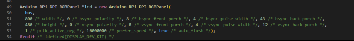
Arduino_RPi_DPI_RGBPanel *lcd = new Arduino_RPi_DPI_RGBPanel(
  bus,
  800 /* width */, 0 /* hsync_polarity */, 210 /* hsync_front_porch */, 4 /* hsync_pulse_width */, 43 /* hsync_back_porch */,
  480 /* height */, 0 /* vsync_polarity */, 22 /* vsync_front_porch */, 4 /* vsync_pulse_width */, 12 /* vsync_back_porch */,
  1 /* pclk_active_neg */, 16000000 /* prefer_speed */, true /* auto_flush */);
#endif /* !defined(DISPLAY_DEV_KIT) */
For 7-inch esp32 screen:
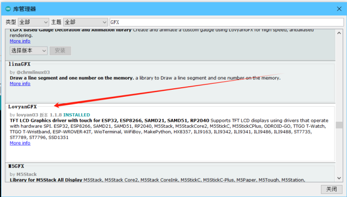
Step 1: Download the LovyanGFX library
Step 2: Modify the code of HMI-7.0
Add the following code:
#include <LovyanGFX.hpp>
#include <lgfx/v1/platforms/esp32s3/Panel_RGB.hpp>
#include <lgfx/v1/platforms/esp32s3/Bus_RGB.hpp>


// Define a class named LGFX, inheriting from the LGFX_Device class.
class LGFX : public lgfx::LGFX_Device {
public:
  // Instances for the RGB bus and panel.
  lgfx::Bus_RGB     _bus_instance;
  lgfx::Panel_RGB   _panel_instance;


  // Constructor for the LGFX class.
  LGFX(void) {
    // Configure the RGB bus.
    {
      auto cfg = _bus_instance.config();
      cfg.panel = &_panel_instance;


      // Configure data pins.
      cfg.pin_d0  = GPIO_NUM_15; // B0
      cfg.pin_d1  = GPIO_NUM_7;  // B1
      cfg.pin_d2  = GPIO_NUM_6;  // B2
      cfg.pin_d3  = GPIO_NUM_5;  // B3
      cfg.pin_d4  = GPIO_NUM_4;  // B4

      cfg.pin_d5  = GPIO_NUM_9;  // G0
      cfg.pin_d6  = GPIO_NUM_46; // G1
      cfg.pin_d7  = GPIO_NUM_3;  // G2
      cfg.pin_d8  = GPIO_NUM_8;  // G3
      cfg.pin_d9  = GPIO_NUM_16; // G4
      cfg.pin_d10 = GPIO_NUM_1;  // G5

      cfg.pin_d11 = GPIO_NUM_14; // R0
      cfg.pin_d12 = GPIO_NUM_21; // R1
      cfg.pin_d13 = GPIO_NUM_47; // R2
      cfg.pin_d14 = GPIO_NUM_48; // R3
      cfg.pin_d15 = GPIO_NUM_45; // R4


      // Configure sync and clock pins.
      cfg.pin_henable = GPIO_NUM_41;
      cfg.pin_vsync   = GPIO_NUM_40;
      cfg.pin_hsync   = GPIO_NUM_39;
      cfg.pin_pclk    = GPIO_NUM_0;
      cfg.freq_write  = 15000000;


      // Configure timing parameters for horizontal and vertical sync.
      cfg.hsync_polarity    = 0;
      cfg.hsync_front_porch = 40;
      cfg.hsync_pulse_width = 48;
      cfg.hsync_back_porch  = 40;

      cfg.vsync_polarity    = 0;
      cfg.vsync_front_porch = 1;
      cfg.vsync_pulse_width = 31;
      cfg.vsync_back_porch  = 13;


      // Configure polarity for clock and data transmission.
      cfg.pclk_active_neg   = 1;
      cfg.de_idle_high      = 0;
      cfg.pclk_idle_high    = 0;


      // Apply configuration to the RGB bus instance.
      _bus_instance.config(cfg);
    }


    // Configure the panel.
    {
      auto cfg = _panel_instance.config();
      cfg.memory_width  = 800;
      cfg.memory_height = 480;
      cfg.panel_width   = 800;
      cfg.panel_height  = 480;
      cfg.offset_x      = 0;
      cfg.offset_y      = 0;


      // Apply configuration to the panel instance.
      _panel_instance.config(cfg);
    }


    // Set the RGB bus and panel instances.
    _panel_instance.setBus(&_bus_instance);
    setPanel(&_panel_instance);
  }
};
LGFX lcd;
and delete the following code:
#include <Arduino_GFX_Library.h>
#define TFT_BL 2
//#define GFX_BL DF_GFX_BL // default backlight pin, you may replace DF_GFX_BL to actual backlight pin


/* More dev device declaration: https://github.com/moononournation/Arduino_GFX/wiki/Dev-Device-Declaration */
#if defined(DISPLAY_DEV_KIT)
Arduino_GFX *lcd = create_default_Arduino_GFX();
#else /* !defined(DISPLAY_DEV_KIT) */


//Arduino_ESP32RGBPanel *bus = new Arduino_ESP32RGBPanel(
//    GFX_NOT_DEFINED /* CS */, GFX_NOT_DEFINED /* SCK */, GFX_NOT_DEFINED /* SDA */,
//    40 /* DE */, 41 /* VSYNC */, 39 /* HSYNC */, 42 /* PCLK */,
//    45 /* R0 */, 48 /* R1 */, 47 /* R2 */, 21 /* R3 */, 14 /* R4 */,
//    5 /* G0 */, 6 /* G1 */, 7 /* G2 */, 15 /* G3 */, 16 /* G4 */, 4/* G5 */,
//    8 /* B0 */, 3 /* B1 */, 46 /* B2 */, 9 /* B3 */, 1 /* B4 */
//);
Arduino_ESP32RGBPanel *bus = new Arduino_ESP32RGBPanel(
  GFX_NOT_DEFINED /* CS */, GFX_NOT_DEFINED /* SCK */, GFX_NOT_DEFINED /* SDA */,
  41 /* DE */, 40 /* VSYNC */, 39 /* HSYNC */, 0 /* PCLK */,
  14 /* R0 */, 21 /* R1 */, 47 /* R2 */, 48 /* R3 */, 45 /* R4 */,
  9 /* G0 */, 46 /* G1 */, 3 /* G2 */, 8 /* G3 */, 16 /* G4 */, 1 /* G5 */,
  15 /* B0 */, 7 /* B1 */, 6 /* B2 */, 5 /* B3 */, 4 /* B4 */
);


// option 1:
// 7寸 50PIN 800*480
Arduino_RPi_DPI_RGBPanel *lcd = new Arduino_RPi_DPI_RGBPanel(
  bus,
  //  800 /* width */, 0 /* hsync_polarity */, 8/* hsync_front_porch */, 2 /* hsync_pulse_width */, 43/* hsync_back_porch */,
  //  480 /* height */, 0 /* vsync_polarity */, 8 /* vsync_front_porch */, 2/* vsync_pulse_width */, 12 /* vsync_back_porch */,
  //  1 /* pclk_active_neg */, 16000000 /* prefer_speed */, true /* auto_flush */);


  //  800 /* width */, 0 /* hsync_polarity */, 40 /* hsync_front_porch */, 48 /* hsync_pulse_width */, 40 /* hsync_back_porch */,
  //  480 /* height */, 0 /* vsync_polarity */, 13 /* vsync_front_porch */, 1 /* vsync_pulse_width */, 31 /* vsync_back_porch */,
  //  1 /* pclk_active_neg */, 16000000 /* prefer_speed */, true /* auto_flush */);
//  800 /* width */, 0 /* hsync_polarity */, 210 /* hsync_front_porch */, 30 /* hsync_pulse_width */, 16 /* hsync_back_porch */,
//  480 /* height */, 0 /* vsync_polarity */, 22 /* vsync_front_porch */, 13 /* vsync_pulse_width */, 10 /* vsync_back_porch */,
//  0 /* pclk_active_neg */, 16000000 /* prefer_speed */, true /* auto_flush */);
  800 /* width */, 0 /* hsync_polarity */, 210 /* hsync_front_porch */, 1 /* hsync_pulse_width */, 46 /* hsync_back_porch */,
  480 /* height */, 0 /* vsync_polarity */, 22 /* vsync_front_porch */, 1 /* vsync_pulse_width */, 23 /* vsync_back_porch */,
  0 /* pclk_active_neg */, 16000000 /* prefer_speed */, true /* auto_flush */);


#endif /* !defined(DISPLAY_DEV_KIT) */
/*******************************************************************************
   End of Arduino_GFX setting
 ******************************************************************************/
modify the following code
/* Display flushing */
void my_disp_flush(lv_disp_drv_t *disp, const lv_area_t *area, lv_color_t *color_p)
{
  uint32_t w = (area->x2 - area->x1 + 1);
  uint32_t h = (area->y2 - area->y1 + 1);


#if (LV_COLOR_16_SWAP != 0)
  lcd->draw16bitBeRGBBitmap(area->x1, area->y1, (uint16_t *)&color_p->full, w, h);
#else
  lcd->draw16bitRGBBitmap(area->x1, area->y1, (uint16_t *)&color_p->full, w, h);
#endif


  lv_disp_flush_ready(disp);
}
into
/* Display flushing */
void my_disp_flush(lv_disp_drv_t *disp, const lv_area_t *area, lv_color_t *color_p)
{


  uint32_t w = (area->x2 - area->x1 + 1);
  uint32_t h = (area->y2 - area->y1 + 1);


  //lcd.fillScreen(TFT_WHITE);
#if (LV_COLOR_16_SWAP != 0)
 lcd.pushImageDMA(area->x1, area->y1, w, h,(lgfx::rgb565_t*)&color_p->full);
#else
  lcd.pushImageDMA(area->x1, area->y1, w, h,(lgfx::rgb565_t*)&color_p->full);//
#endif


  lv_disp_flush_ready(disp);


}
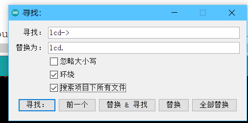
Step 3: Use the quick search function(Ctrl+F) to replace lcd-> in the code with lcd.
👉️Back to FAQ page👈️
Comments
I simply can not get the 7 inch Elecrow HMI display to work properly. I also have the 5 inch and it works great! But nothing but problems with the 7 inch. I've been using the Arudino_GFX library and my sketch will work for a while then the screen goes blank. Then my sketch will display again, then blank screen again. I've tried switching over to LovyanGFX and create the simplest "Hello World" sketch possible. it compiles fine, but I just get a blank screen. Can someone look at my code below which mostly came from the information above and tell me what is wrong? Or perhaps Elecrow could provide a super simple Hello World sketch that works?
Thanks,
Jeff
#define LGFX_USE_V1
#include <LovyanGFX.hpp>
#include <lgfx/v1/platforms/esp32s3/Panel_RGB.hpp>
#include <lgfx/v1/platforms/esp32s3/Bus_RGB.hpp>
// Define a class named LGFX, inheriting from the LGFX_Device class.
class LGFX : public lgfx::LGFX_Device {
public:
// Instances for the RGB bus and panel.
lgfx::Bus_RGB _bus_instance;
lgfx::Panel_RGB _panel_instance;
// Constructor for the LGFX class.
LGFX(void) {
// Configure the RGB bus.
{
auto cfg = _bus_instance.config();
cfg.panel = &_panel_instance;
// Configure data pins.
cfg.pin_d0 = GPIO_NUM_15; // B0
cfg.pin_d1 = GPIO_NUM_7; // B1
cfg.pin_d2 = GPIO_NUM_6; // B2
cfg.pin_d3 = GPIO_NUM_5; // B3
cfg.pin_d4 = GPIO_NUM_4; // B4
cfg.pin_d5 = GPIO_NUM_9; // G0
cfg.pin_d6 = GPIO_NUM_46; // G1
cfg.pin_d7 = GPIO_NUM_3; // G2
cfg.pin_d8 = GPIO_NUM_8; // G3
cfg.pin_d9 = GPIO_NUM_16; // G4
cfg.pin_d10 = GPIO_NUM_1; // G5
cfg.pin_d11 = GPIO_NUM_14; // R0
cfg.pin_d12 = GPIO_NUM_21; // R1
cfg.pin_d13 = GPIO_NUM_47; // R2
cfg.pin_d14 = GPIO_NUM_48; // R3
cfg.pin_d15 = GPIO_NUM_45; // R4
// Configure sync and clock pins.
cfg.pin_henable = GPIO_NUM_41;
cfg.pin_vsync = GPIO_NUM_40;
cfg.pin_hsync = GPIO_NUM_39;
cfg.pin_pclk = GPIO_NUM_0;
cfg.freq_write = 15000000;
// Configure timing parameters for horizontal and vertical sync.
cfg.hsync_polarity = 0;
cfg.hsync_front_porch = 40;
cfg.hsync_pulse_width = 48;
cfg.hsync_back_porch = 40;
cfg.vsync_polarity = 0;
cfg.vsync_front_porch = 1;
cfg.vsync_pulse_width = 31;
cfg.vsync_back_porch = 13;
// Configure polarity for clock and data transmission.
cfg.pclk_active_neg = 1;
cfg.de_idle_high = 0;
cfg.pclk_idle_high = 0;
// Apply configuration to the RGB bus instance.
_bus_instance.config(cfg);
}
// Configure the panel.
{
auto cfg = _panel_instance.config();
cfg.memory_width = 800;
cfg.memory_height = 480;
cfg.panel_width = 800;
cfg.panel_height = 480;
cfg.offset_x = 0;
cfg.offset_y = 0;
// Apply configuration to the panel instance.
_panel_instance.config(cfg);
}
// Set the RGB bus and panel instances.
_panel_instance.setBus(&_bus_instance);
setPanel(&_panel_instance);
}
};
LGFX lcd;
void setup() {
lcd.init();
lcd.setRotation(1);
lcd.setBrightness(255);
lcd.setColorDepth(16); // RGB565の16
lcd.fillScreen(lcd.color565(0,0,0));
lcd.fillScreen(lcd.color565(255,255,255));
lcd.setCursor(10, 30);
lcd.setTextColor(lcd.color565(255,255,255));
lcd.println("Hello World!");
lcd.drawRect(0, 0, 800, 480, lcd.color565(0,255,0));
}
void loop() {
}
@JeffRH are you still struggling? I got the 7" screen to work with LovyanGFX a while ago. I can share a full sketch if it would help you?
Hello benlye
I am have difficulty with the 7 inch Display as well. If you could share you code it would be much appreciated.
Thanks, Les
Hello @JeffRH ,
According to your program, you set the background to be black and then turn white, and the text to be white.
You can comment out
lcd.fillScreen(lcd.color565(255,255,255));and see if it will show "Hello World!" on the screen.
Or you can also try the Hello World program provided bellow:
The sketch below works for me on the 7" screen.
My IDE Settings (Arduino IDE 2.2.1):
The IDE settings are important. E.g., with PSRAM disabled (instead of OPI) the screen is just black.
#define LGFX_USE_V1 #include <LovyanGFX.hpp> #include <lgfx/v1/platforms/esp32s3/Panel_RGB.hpp> #include <lgfx/v1/platforms/esp32s3/Bus_RGB.hpp> #include <driver/i2c.h> class LGFX : public lgfx::LGFX_Device { public: lgfx::Bus_RGB _bus_instance; lgfx::Panel_RGB _panel_instance; lgfx::Light_PWM _light_instance; lgfx::Touch_GT911 _touch_instance; LGFX(void) { { auto cfg = _panel_instance.config(); cfg.memory_width = 800; cfg.memory_height = 480; cfg.panel_width = 800; cfg.panel_height = 480; cfg.offset_x = 0; cfg.offset_y = 0; _panel_instance.config(cfg); } { auto cfg = _bus_instance.config(); cfg.panel = &_panel_instance; cfg.pin_d0 = GPIO_NUM_15; // B0 cfg.pin_d1 = GPIO_NUM_7; // B1 cfg.pin_d2 = GPIO_NUM_6; // B2 cfg.pin_d3 = GPIO_NUM_5; // B3 cfg.pin_d4 = GPIO_NUM_4; // B4 cfg.pin_d5 = GPIO_NUM_9; // G0 cfg.pin_d6 = GPIO_NUM_46; // G1 cfg.pin_d7 = GPIO_NUM_3; // G2 cfg.pin_d8 = GPIO_NUM_8; // G3 cfg.pin_d9 = GPIO_NUM_16; // G4 cfg.pin_d10 = GPIO_NUM_1; // G5 cfg.pin_d11 = GPIO_NUM_14; // R0 cfg.pin_d12 = GPIO_NUM_21; // R1 cfg.pin_d13 = GPIO_NUM_47; // R2 cfg.pin_d14 = GPIO_NUM_48; // R3 cfg.pin_d15 = GPIO_NUM_45; // R4 cfg.pin_henable = GPIO_NUM_41; cfg.pin_vsync = GPIO_NUM_40; cfg.pin_hsync = GPIO_NUM_39; cfg.pin_pclk = GPIO_NUM_0; cfg.freq_write = 12000000; cfg.hsync_polarity = 0; cfg.hsync_front_porch = 40; cfg.hsync_pulse_width = 48; cfg.hsync_back_porch = 40; cfg.vsync_polarity = 0; cfg.vsync_front_porch = 1; cfg.vsync_pulse_width = 31; cfg.vsync_back_porch = 13; cfg.pclk_active_neg = 1; cfg.de_idle_high = 0; cfg.pclk_idle_high = 0; _bus_instance.config(cfg); } _panel_instance.setBus(&_bus_instance); { auto cfg = _light_instance.config(); cfg.pin_bl = GPIO_NUM_2; _light_instance.config(cfg); } _panel_instance.light(&_light_instance); { auto cfg = _touch_instance.config(); cfg.x_min = 0; cfg.x_max = 799; cfg.y_min = 0; cfg.y_max = 479; cfg.pin_int = -1; cfg.pin_rst = -1; cfg.bus_shared = false; cfg.offset_rotation = 0; cfg.i2c_port = I2C_NUM_1; cfg.pin_sda = GPIO_NUM_19; cfg.pin_scl = GPIO_NUM_20; cfg.freq = 400000; cfg.i2c_addr = 0x14; _touch_instance.config(cfg); _panel_instance.setTouch(&_touch_instance); } setPanel(&_panel_instance); } }; LGFX lcd; void setup() { Serial.begin(115200); Serial.println(); Serial.println("LCD Init."); lcd.init(); lcd.setBrightness(255); lcd.fillScreen(TFT_WHITE); delay(250); lcd.fillScreen(TFT_RED); delay(250); lcd.fillScreen(TFT_GREEN); delay(250); lcd.fillScreen(TFT_BLUE); delay(250); lcd.fillScreen(TFT_BLACK); lcd.setTextSize((std::max(lcd.width(), lcd.height()) + 255) >> 8); lcd.setTextDatum(textdatum_t::middle_center); lcd.drawString("touch the screen", lcd.width() >> 1, lcd.height() >> 1); } void loop() { int32_t x, y; if (lcd.getTouch(&x, &y)) { Serial.printf("X:%d Y:%d\n",x, y); lcd.fillCircle(x, y, 15, TFT_WHITE); } delay(100); }THANKS! Yes finally something with Lovyan that works. Now I'm trying to implement a simple sprite. I've tried many things. I've studied the Lovyan github examples, but I just get blank screen. My sketch works fine without the sprites, but the screen blinks because I'm updating it very quickly. It makes quite a nice visual. Do you have a super simple implementation of this example but using a sprite?
Here is a link to my project without the sprite attempt. It works great. Nice visuals, aside from the blinking.
https://app.box.com/s/fb9p9d6cs2n4dyaawxy2lw352jld3g5k
Here is a link with my sprite attempt:
https://app.box.com/s/lcdzm7bhpgw2hi47v1h7phhh0tfwxayl
Thank you so much for your help!
Jeff
Finally got this screen working with BenLye and Elecrow's assistance.
Here is my updated code for any others trying to use this screen with Squareline. Should work with all Squareline Studio UI's, just keep the .ino and touch.h files the same but replace all of my ui files with yours.
https://github.com/jrodanapolis/WE-UI_SLS
For anyone attempting to use benlye's sketch above on the the 5" version, the LCD pinouts are different.
I've found the following snippet works:
{
            auto cfg = _bus_instance.config();
            cfg.panel = &_panel_instance;
            /* Config updated for 5" panel */


            cfg.pin_d0 = GPIO_NUM_8; // B3
            cfg.pin_d1 = GPIO_NUM_3;  // B4
            cfg.pin_d2 = GPIO_NUM_46;  // B5
            cfg.pin_d3 = GPIO_NUM_9;  // B6
            cfg.pin_d4 = GPIO_NUM_1;  // B7


            cfg.pin_d5 = GPIO_NUM_5;  // G2
            cfg.pin_d6 = GPIO_NUM_6; // G3
            cfg.pin_d7 = GPIO_NUM_7;  // G4
            cfg.pin_d8 = GPIO_NUM_15;  // G5
            cfg.pin_d9 = GPIO_NUM_16; // G6
            cfg.pin_d10 = GPIO_NUM_4; // G7


            cfg.pin_d11 = GPIO_NUM_45; // R3
            cfg.pin_d12 = GPIO_NUM_48; // R4
            cfg.pin_d13 = GPIO_NUM_47; // R5
            cfg.pin_d14 = GPIO_NUM_21; // R6
            cfg.pin_d15 = GPIO_NUM_14; // R7


            cfg.pin_henable = GPIO_NUM_40;
            cfg.pin_vsync = GPIO_NUM_41;
            cfg.pin_hsync = GPIO_NUM_39;
            cfg.pin_pclk = GPIO_NUM_0;
            cfg.freq_write = 8000000;


            cfg.hsync_polarity = 0;
            cfg.hsync_front_porch = 40;
            cfg.hsync_pulse_width = 48;
            cfg.hsync_back_porch = 40;


            cfg.vsync_polarity = 0;
            cfg.vsync_front_porch = 1;
            cfg.vsync_pulse_width = 31;
            cfg.vsync_back_porch = 13;


            cfg.pclk_active_neg = 1;
            cfg.de_idle_high = 0;
            cfg.pclk_idle_high = 0;


            _bus_instance.config(cfg);
        }
        _panel_instance.setBus(&_bus_instance);
Now to get it working with LVGL.
Hi there!") Thx benlye! When I try the squareline example you gave I get some weird things on the 5" display. Anyone had those issues too and knows something that helps?
Thx benlye! When I try the squareline example you gave I get some weird things on the 5" display. Anyone had those issues too and knows something that helps? ")
Finaly I was able to upload just SOMETHING to my panel
The serial Monitor is showing some errors:
E (394) gpio: gpio_set_level(227): GPIO output gpio_num error
E (395) gpio: gpio_set_level(227): GPIO output gpio_num error
E (405) gpio: gpio_set_level(227): GPIO output gpio_num error
E (459) gpio: gpio_set_level(227): GPIO output gpio_num error
E (528) gpio: gpio_set_level(227): GPIO output gpio_num error
Setup done
Thank you very much!
Best wishes
Tobi
Hello @Tobi1012 ,
May I kindly ask did you got the weird thing when receiving and powering the display? Please try to upload the demo code and check if the issues will disappear. Here's the download link of demo code: https://www.elecrow.com/download/product/ESP32_Display/5.0inch/Arduino_5inch.zip
Besides, the reason why the error message appears is that the initialization pin and reset pin of the touch are not configured. There are not enough gpio allocated to the touch, so this error message cannot be eliminated, but it will not affect the normal use of the touch.