

Lora RA-08H: can't read/write PINs

I connected two crowtail "Button 2.0" via D0 and D1 to the board. These should be PIN 2+3. I'm setting the pinMode to INPUT. A digitalRead() always reads HIGH, no matter if the buttons are pressed or even connected. I even tried another RA-08H with the same behavior. Using Arduino IDE with RPI Pico as Board after setting the boards manager URL to the given one for rp2040.
Reading from PIR or using and LED-Bar didn't work either.
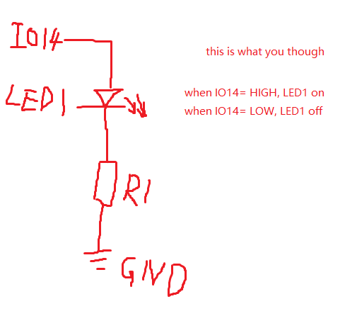
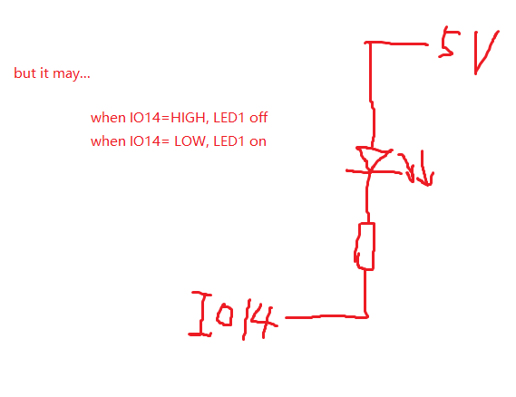
I also noticed, that setting the LED to HIGH should turn it ON. But LOW turns it on.
Hints anyone?
#define BUTTON_0 2

int buttonState0 = 1;

void setup() {
  Serial.begin(9600);
  pinMode(LED_BUILTIN, OUTPUT);
  pinMode(BUTTON_0, INPUT);
}

void loop() {
  digitalWrite(LED_BUILTIN, LOW);  // LOW => ON
  delay(100);
  digitalWrite(LED_BUILTIN, HIGH); // HIGH => OFF

  buttonState0 = digitalRead(BUTTON_0);
  Serial.print("****");
  Serial.print("\n");
  Serial.print("bs0: ");
  Serial.print(buttonState0);
  Serial.print("\n");

  if (buttonState0 == HIGH) {
    // turn LED on:
    digitalWrite(LED_BUILTIN, LOW);
  } else {
    // turn LED off:
    digitalWrite(LED_BUILTIN, HIGH);
  }

  delay(1000);
}
Comments
Hello @KMiller ,
Thank you for your information.
"A digitalRead() always reads HIGH, no matter if the buttons are pressed or even connected."
-This is because the pin definition of the button is incorrect. You can see from the silkscreen of the board that D0 corresponds to GPIO14 and D1 corresponds to GPIO15, so
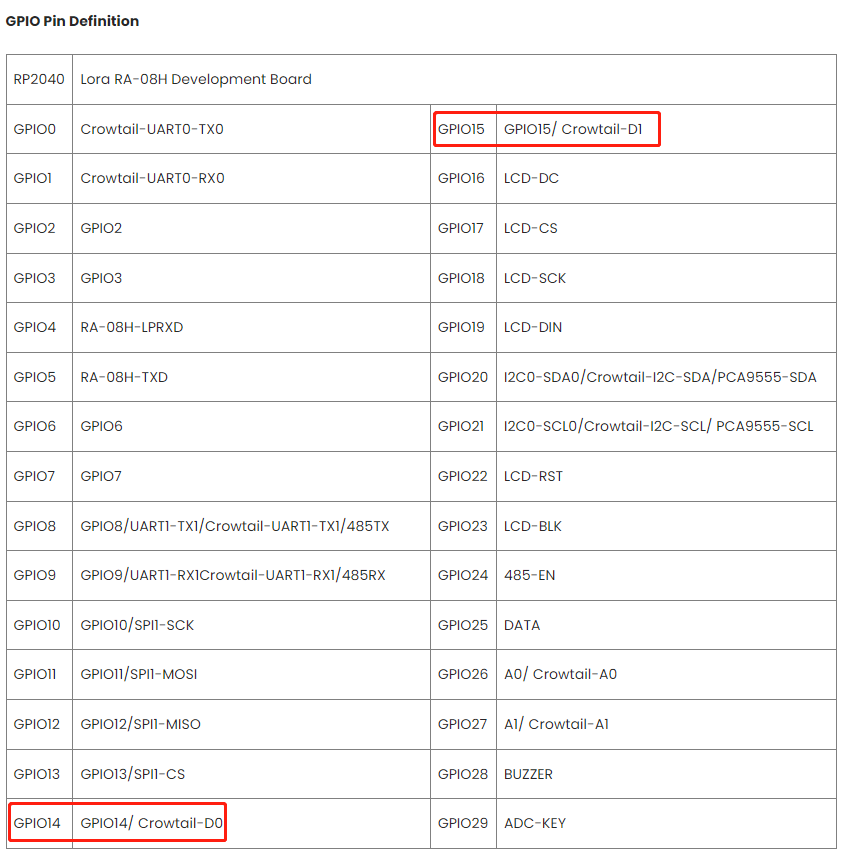
#define BUTTON_0 2should be changed to#define BUTTON_0 14(if you connected to D0)Regarding the triggering conditions of the LED, it is not necessarily a high level that lights the LED. Whether it is a high level or a low level that lights the LED depends on the circuit.
Thanks for the fast reply.
14/15 are always LOW. I don't have the Development Board but the Node Board: https://wiki.elecrow.com/index.php?title=Lora_RA-08H_Node_Board
I guess this changes the pins? Maybe a list of pins (or a link to the specs) would be nice on this wiki page. At least I tried to find them and couldn't figure it out.
Thanks for the clarification about the LED. As I went through the example code with LED_BUILTIN, I Just expected it to be the other way around like it's in the code comments. For future reference: this is pin 25.
Out of despair I looped through all pins from 0 to 50 (except 25), set them to INPUT and read all of them in a second loop. Pushing the buttons didn't change any values (even though some are 0 some are 1). Also tried INPUT_PULL with no change at all.
Even tried a second board.
I can measure the expected 5V on D0 and D1. At the button itself it is 1.6V difference. Between GND and SIG I get 5V when pressed and 3.4V when not-pressed.
After 3 days of trial and error we made some progress. This was highly frustrating because connecting a simple button to a digital input within the crowtail familiy should be super easy. To save others the hassle:
analogRead(A0)works.Grove_LED_Bar bar(9, 8, 0, LED_BAR_10); // Clock pin, Data pin, Orientation