

Universal LCD I2C adapter board---Solve multi-line connection problems

✍️Character LCDs are a fantastic and cost-effective option when your project calls for a user-friendly output method. Besides being cheap and easy to use, these displays often offer enough usable screen real-estate for displaying simple status messages and interactive menu screens.
?However, the standard 16-pin interface can be quite a hassle to work with, and all the wires quickly clutter up your previously simple Arduino project. While there are some I2C character LCDs out in the wild, these models are often more expensive and sometimes difficult to work with.
?Therefore, I decided to build a simple-to-use alternative that allows you to control pretty much any standard 14 and 16-pin LCD display with only four wires.
?♀️Using a character LCD with an Arduino (or any other MCU for that matter) typically requires you to connect four supply wires, three control lines, and eight parallel data lines. An additional analog input pin allows you to adjust the contrast.
?Note that most displays let you use only four data wires. In that case, you’ll have to transmit the display command using two half-bytes. In addition, some LCDs only have fourteen input pins due to the absence of an LED backlight. Sometimes, the backlight is already internally connected to the logic-supply pins.
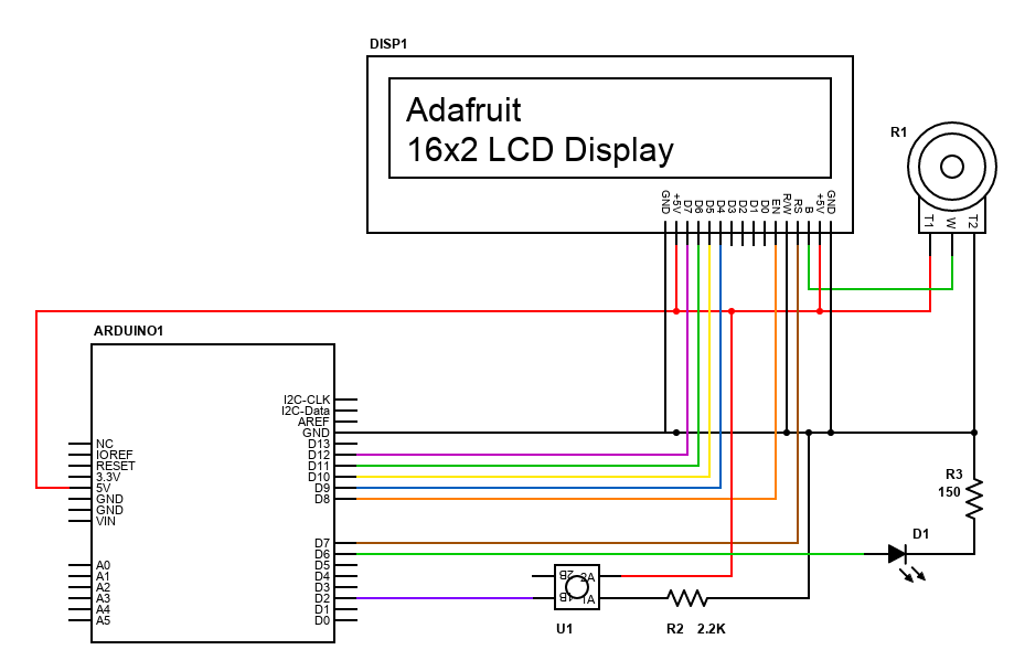
❤️Figure 1: A simple project that utilizes a standard 16×2 character LCD. Note the large number of GPIO pins that the display occupies.
✋As the example in fig. 1 shows, using the four-wire method reduces the number of occupied GPIO pins. However, you’ll still have to make quite a few connections, which makes working with a character LCD more troublesome than it should be. My goal for this project is to make the schematic look something like this:
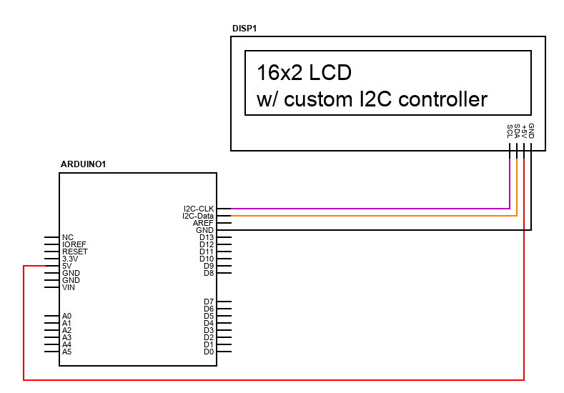
?Figure 2: The goal of this project is to build a simple I2C interface that makes it easier to use standard character LC-displays with an Arduino. Note how this set up only requires two communication lines (pull-up resistors omitted) and two power wires.
?Note that I also want to remove the need for an external contrast-adjustment potentiometer. Instead, I want to include it on the finished expansion board. I think it’s also a good idea to add a few buttons or a simple beeper next to the display. However, I’ll omit those here as my main focus is to build a display adapter board that makes it easier to use a standard character LCD in Arduino projects.
?I’d also like to mention that I’ll only utilize the display to show standard ASCII characters. Therefore, I’ll ignore custom characters in this project. However, you can change the software to include custom characters if you need them in your project.
Code / Circuit diagrams and Schematics::