

Leader-Follower Robot Legs---Arduino project sharing

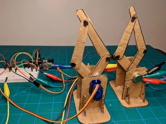
In this project we will be building two robot legs. One - the leader leg - will use potentiometers to determine its current position and communicate that to the Arduino, and the other - the follower leg - will use a servo to move the leg. By connecting the leader and follower legs together, you can create a “leader-follower” robot, where the follower leg mirrors (follows) the movement of the leader leg. By moving the leader leg by hand (kind of like a joystick) you can precisely control the motion of the follower.
Supplies✍️
Components Used:
Arduino Uno
Micro Servo Motor (2x)
Potentiometer (2x)
Jumper Wires
Alligator Clips/Wires
Breadboard (Optional)
Pipe Cleaners
Cardboard
Tools Used:
Phillips Head Screwdriver (Optional)
Laser Cutter (Optional)
Hot Glue Gun
Software Used:
Arduino IDE
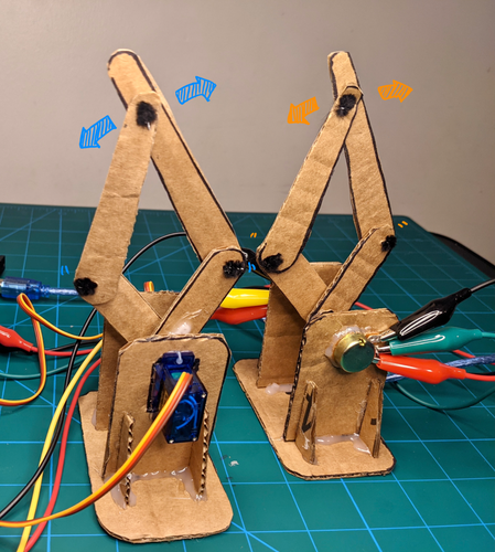
Step 1: Follower Leg Overview✍️

The first component we will build is the follower leg. This leg is controlled by an Arduino microcontroller and moved using two servo motors.
To build the follower leg, you will first construct the leg out of cardboard. Then, you will attach servo motors to the leg that can be controlled with an Arduino. Finally, using the provided sketches, you will see how different servo commands can move the leg along specific paths like ovals and lines.
Step 2: Cut Out the Follower Leg Parts✍️
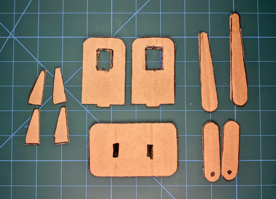
The follower and leader legs are constructed out of cardboard. If you are using a laser cutter, see the attached DXF file. You will need to confirm you have all the pieces pictured above for the follower leg.
If you are cutting the parts out yourself, you can print a cutting template from the attached PDF. After cutting the template out, you can either trace it onto the cardboard or use a glue stick to attach the template on directly. We've also attached a STEP model file if you want to edit or view the 3D design in Fusion 360 (or your CAD program of choice).
For the best results use an Exacto knife, but scissors will also work. The parts featured in this tutorial were cut out by hand.
Step 3: Build the Follower Leg✍️
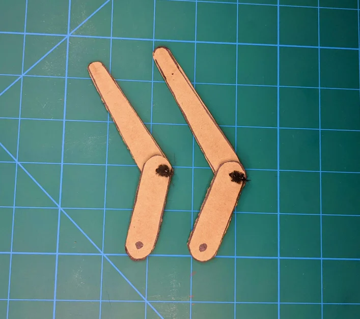
The first component you will build is the follower leg, which is driven by servo motors. We will use pipe cleaners to create the rotating joints on the follower and leader leg.
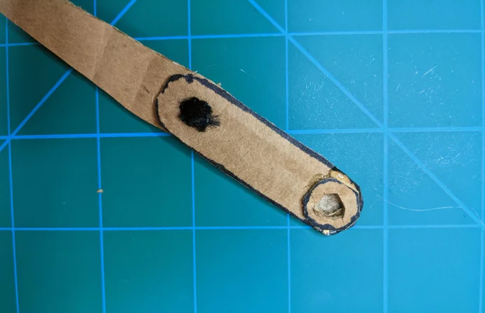
To create the joints, you can use a pin to create holes in the cardboard pieces marked with dots in the cutting templates. Then, use small pieces of pipe cleaner to connect the parts as shown. The pipe cleaner should be just long enough to be inserted through two pieces of cardboard and bent on both sides to secure them together.
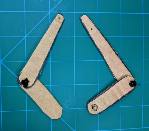
The follower leg is assembled as shown above. Each side of the follower leg has a shorter and wider piece at the bottom and a longer tapered piece at the top. The tips of the longer pieces are then secured with a pipe cleaner joint to secure the halves together. Make sure to stack the leg pieces on top of each other exactly as shown in the pictures. This will make sure that your follower leg comes together properly when fully assembled.
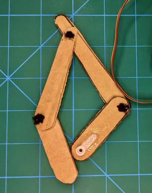
Next, attach a servo horn to the bottom of each half of the follower leg.
The servo horn is a small piece of white plastic that comes with the servo. You may have a few options, but the best is the horn which only extends in one direction (see above). Hot glue the servo horns to the bottom of the leg as shown. Note that only one servo horn is visible in the picture, but there is an identical horn glued onto the other side of the leg.
Step 4: Build the Motor Mounts✍️
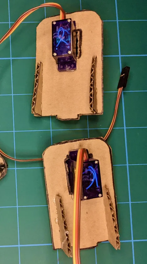
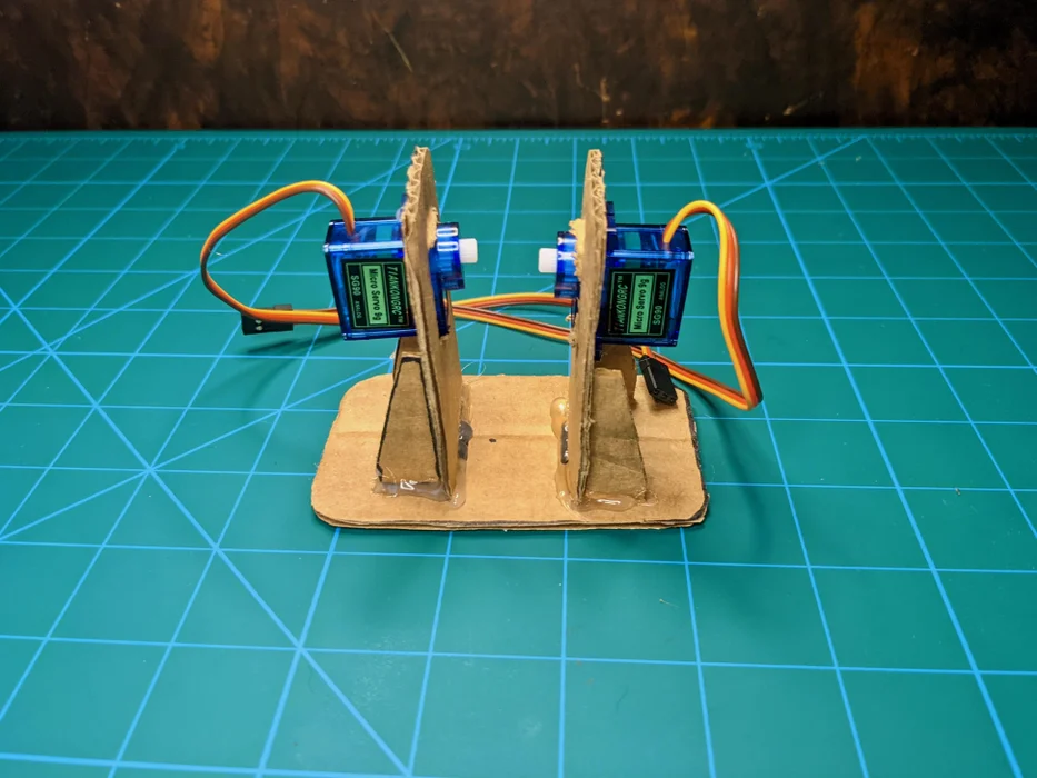
Use hot glue to secure the servos into the rectangular holes on each side piece. The servo motors should be oriented as seen in the image. Also glue in the side braces as shown.
Step 5: Set Up Servo Motors✍️
Once you have the motor mounts built, you will need to set up the servo motors. Each servo motor has a limited range of positions it can move through (roughly 0 - 180 degrees). In order for the leg to move properly, you need to make sure that the servos are in the correct starting position before you attach the leg.
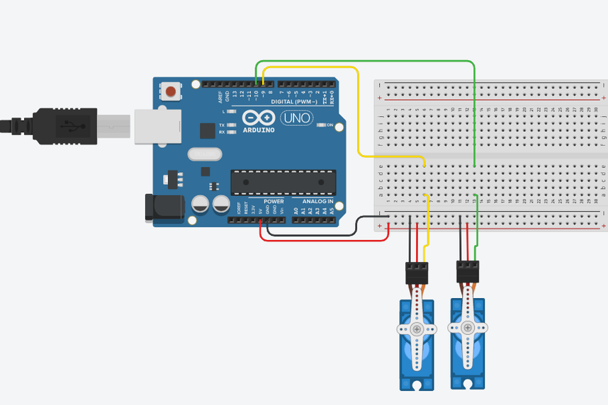
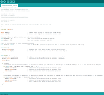
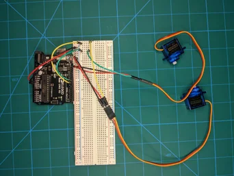
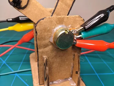
To control the servos you will first need to connect them to the Arduino. This is done in the same way we did in the Servo Creature project. The red wire will be connected to the 5V rail using jumper cables, the black to the GND rail, and the yellow to a PWM pin (for our setup we use 9 and 10 for each servo). Reference the diagram above if you need guidance for wiring. Use the attached sketch to set the leg to different positions and to sweep through the full range of movement. For now, just set each servo to 90 degrees so they are in the right position to be attached to the leg assembly.
(Note: the image above shows the servos connected prior to assembling the side, I found it was best to perform this step after constructing the side piece)
Step 6: Build the Follower Leg Base✍️
With the servos at 90 degrees, you can attach the motor mounts to the base piece. Insert the side pieces into the holes in the base with the servos pointing inwards as shown and hot glue all the pieces together.
Step 7: Attach the Follower Leg✍️
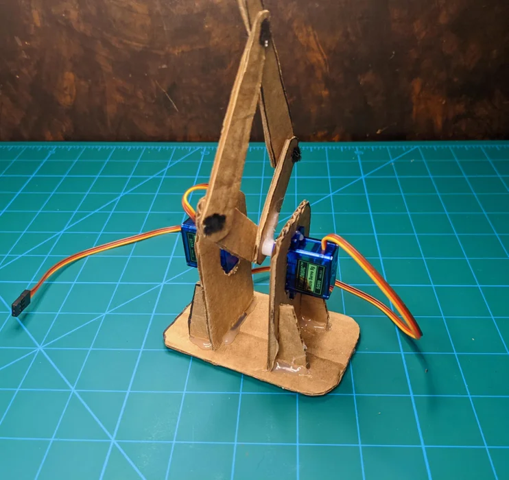
Attach the follower leg assembly to the servos as shown by pressing the servo horns onto the servo motors. The leg should be attached to the motors in a slightly bent position, with the base leg linkages at approximately 45 degrees. The servo motors should also still be at their 90 degree positions. If this step is completed correctly, the follower leg should be able to move freely without crashing into the base mount. Don’t worry if your leg crashes or moves unexpectedly when you first try this step. You will likely have to remount the leg at least once to get the full range of motion. Just keep experimenting!
Step 8: Control the Follower Leg✍️

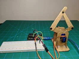
You have fully constructed the follower leg! To connect it to the Arduino, plug it back in using the same diagram as the servo setup step. Red and black wires to 5V and GND respectively, yellow to PWM pins. Reference the diagram above for a single servo connection (you will need to do this for both).
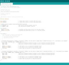
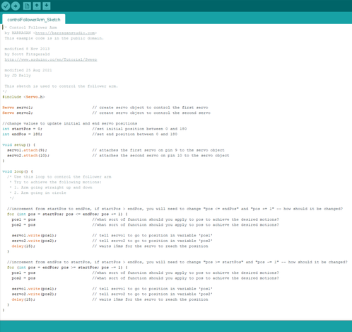
With the leg connected to the Arduino, download the attached sketch to control the leg. See if you can get the leg to move straight up and down, then get it to move in a circle. The comments in the code will highlight where to make changes. If you cannot figure it out, that is alright. Building the leader leg will provide insight on how to do this.
Step 9: Leader Leg Overview✍️
The next part of this project is building the leader leg.
Most of the construction is similar to the follower leg. Pay attention to small changes due to the use of potentiometers to measure the position of the leg rather than servos to move it. This will build on our knowledge of Arduinos and potentiometers. Once you’ve completed the leader leg, you can move it by hand and see how different paths correspond to different potentiometer positions. This will help you understand how to code the follower leg to move in more complex paths.
Step 10: Intro to Potentiometers✍️
In the Servo Creature project, you were briefly introduced to potentiometers. Since this project relies on them much more, we will provide a little more information on how they work.
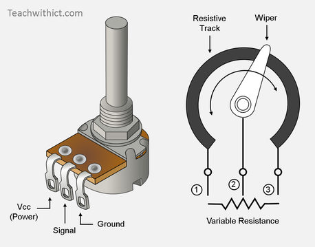
A potentiometer is essentially a variable resistor. If you turn the potentiometer knob one way, the resistance between the signal contact and ground increases. If you turn it the other way, the resistance between the signal contact and ground decreases. For those of you who are somewhat familiar with electronics, this property allows a potentiometer to be used as a “voltage divider.” It’s okay if you don’t know what this means. All you need to know is that, if the potentiometer is wired up as pictured in this tutorial, it will output different voltages based on the position of the potentiometer knob. By reading this voltage with an Arduino, we can use potentiometers as simple position sensors. Pretty cool right?!
The signal wire of the potentiometer is connected to an Arduino analog input pin, which reads the output of the potentiometer as a value between 0 and 1023. This range corresponds to 0-5 volts. These values are how the Arduino interprets position from the potentiometer.
Step 11: Cut Out Leader Leg Parts✍️
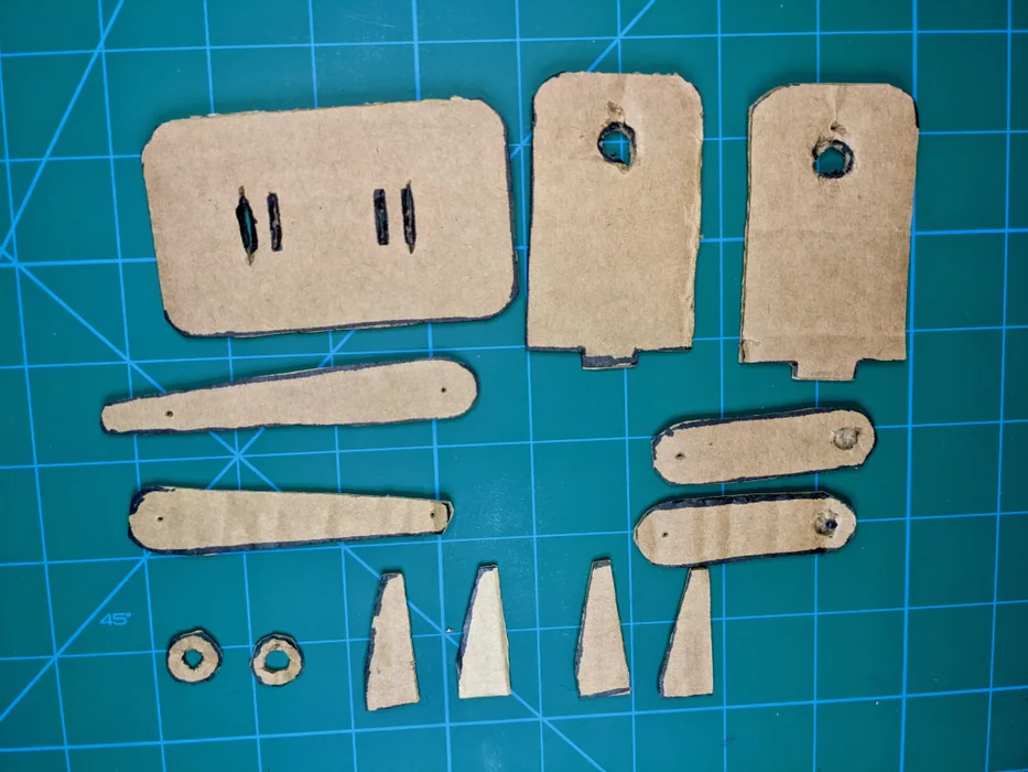
Similar to the follower leg, the leader leg will be constructed out of cardboard. If you are using a laser cutter, see the attached DXF file. You will need to confirm you have all the pieces pictured above. There are some minor differences in the leader leg compared to the follower leg - notice the base, sides, and small circles.
A PDF cutting template for the leader leg is also attached if you are hand cutting the cardboard. We've also attached a STEP model file if you want to edit or view the 3D design in Fusion 360 (or your CAD program of choice).
Step 12: Build the Leader Leg✍️
The leader leg is very similar to the follower leg. The only difference is that the leader leg is mounted to potentiometers instead of servo horns. For the leader leg, glue in the cardboard rings that you cut out earlier in the same positions that you glued in the servo horns for the follower leg. These rings will allow you to mount the potentiometer knob later on. Also, don’t connect the two halves of the leader leg with a piece of pipe cleaner yet.
Step 13: Build Potentiometer Mounts✍️
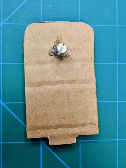
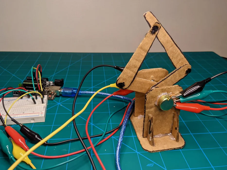
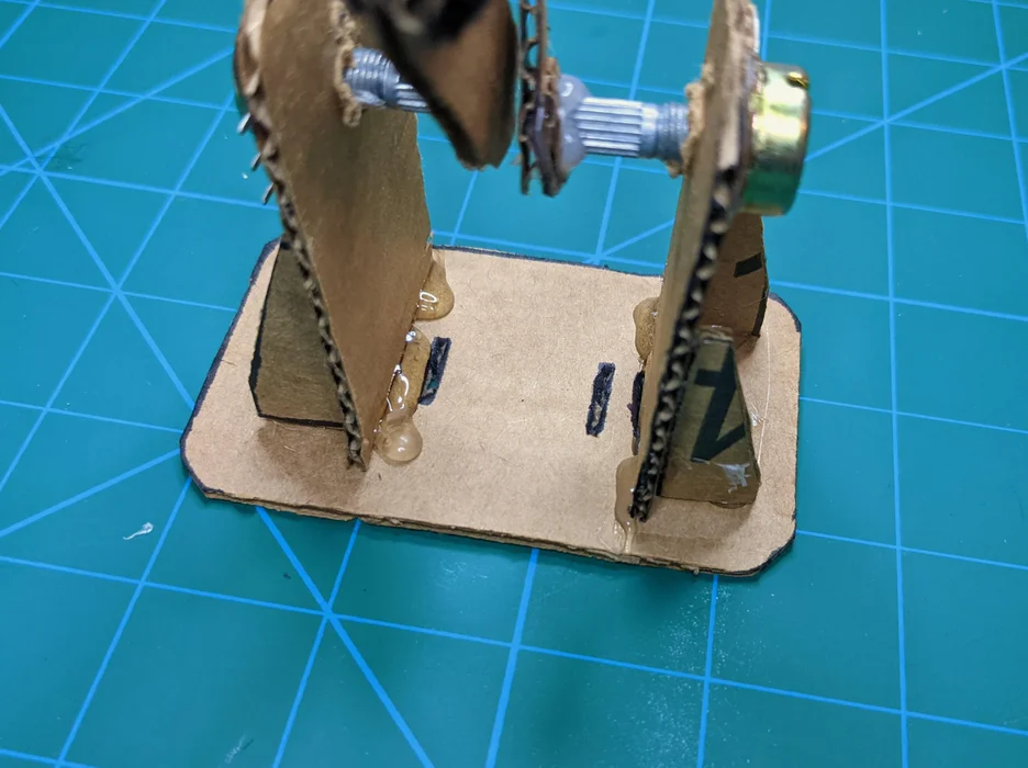
Use hot glue to secure the potentiometers into each side piece. The metal leads of the potentiometers should be pointed to the right when viewed from the back of the potentiometer mounts. See the pictures above for reference. Complete this step for both potentiometers.
Step 14: Set Up Potentiometers✍️
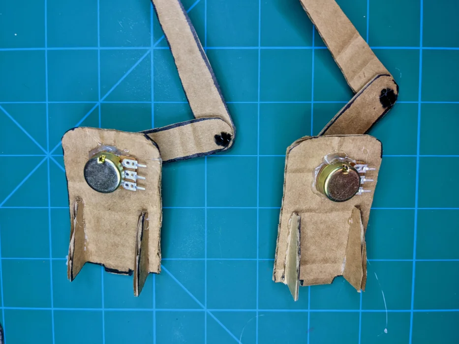
Similar to the servos in the follower arm, the potentiometers in the leader arm must be set to the correct initial positions before being attached to the leader leg. Like the servo motors, you want the potentiometers to be in the middle of their range of motion before mounting them. You can estimate the middle point of the potentiometers by rotating them in both directions until their knobs stop turning. Then, rotate the potentiometers into approximately their middle positions. After you have set the potentiometers, glue in the leader leg halves with the base linkage at approximately 45 degrees as shown. Use plenty of hot glue to make sure that you have created a strong joint.
Step 15: Build the Leader Leg Base✍️
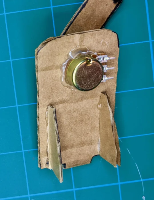
With the potentiometers attached, you can build the base. Insert the side pieces into the holes in the base with the potentiometers pointing inwards and secure two supports to the back of each side with hot glue.
You will notice there are two sets of holes in the base. This is to accommodate different kinds of potentiometers. Use the holes that keep the base and the leg assemblies parallel - the outer holes will work for most potentiometers.
Step 16: Finish the Leader Leg✍️
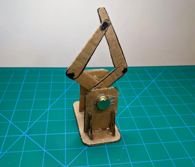
Once set up, you should have half of the full leader leg on each side of the base. You will use another short pipe cleaner piece to connect these two halves at the top, just like the follower leg. Pay special attention to how the leg linkages are stacked in the picture above.
Move the leg around by hand to confirm it can reach all sorts of positions.
Step 17: Read Leader Leg Values✍️
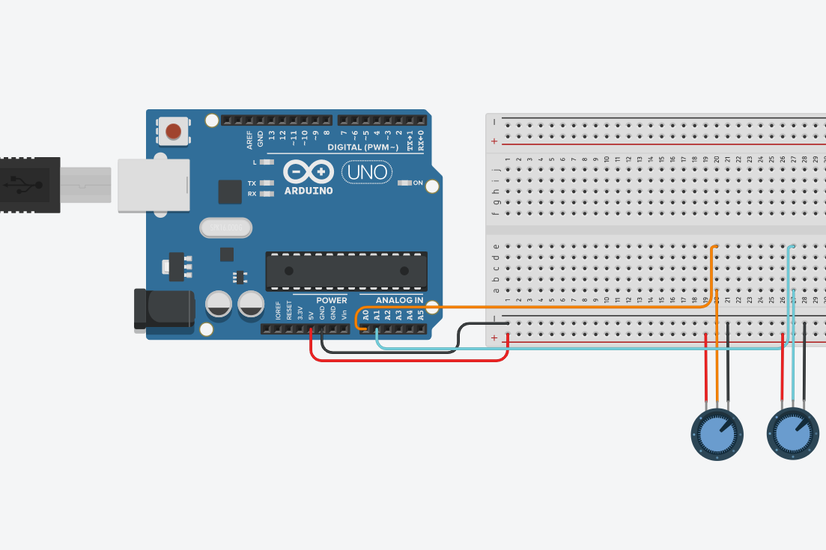
You have now assembled the leader leg! To start getting position values you will need to connect the potentiometers to the Arduino. You will connect the potentiometers in the same way you did for the previous project: connect the bottom pin on the potentiometers to the 5V rail with alligator clips and a jumper wire, the top pin to the GND rail, and the middle to an Analog pin on the Arduino (we used 0 and 1 for our potentiometers). You can reference the diagram above.
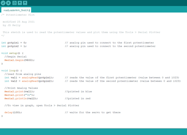
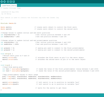
Once connected, you can load the attached sketch to the Arduino to read off the values of the leg. If you open the serial plotter (go to Tools>Serial Plotter in the top bar), it should plot the position of the potentiometers. Use this sketch to fully understand the values the potentiometer reads as the leg sweeps through its range of motion.
Step 18: Return to the Follower Leg✍️
Use the values from the potentiometer experiment to figure out how to get the servo to move straight up and down and in a circle. Return to the follower leg sketch and try to code in these movements. Trigonometry functions might be helpful to make your leg move in an oval or circle. I have attached the Arduino sketch again for easy access.
Step 19: Follower and Leader Legs Overview✍️

You have built both legs, learned to control the servos, and seen the readouts from the potentiometers. Now you will connect both legs so that as you move the leader leg by hand, the follower leg will mimic (or follow) all of the leader’s movements.
Step 20: Putting the Follower and Leader Leg Together✍️
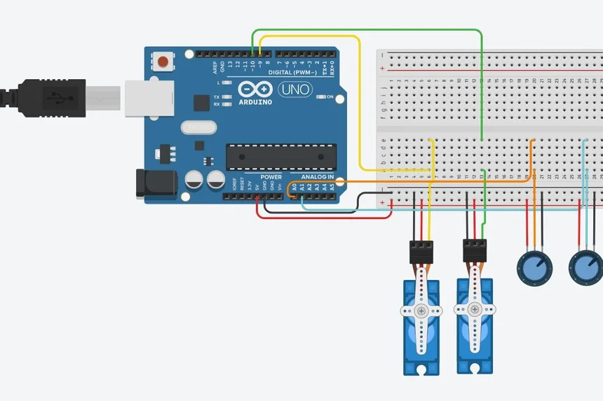
Connect both of the legs to the Arduino using the same pins from earlier (pins 9 and 10 for the servos and pins 0 and 1 for the potentiometers). If you need help connecting everything to the servo, reference the diagram and photos from this step.
Load the attached sketch to the Arduino to get the follower leg to mirror how you move the leader leg. There are some placeholders in the code you will need to change before you can load the sketch. Remember that you may have made some adjustments to the start and end positions to achieve your desired range of motion. If the movement of leader and follower do not match, it is likely because you did not update these positions.
Step 21: Finished!✍️
That is it! Mess around with it and see the legs move in unison. Thanks for sticking with the project and I hope you enjoyed it.
You will continue to build on these skills as you work through future projects.
Special note: The author of the above article is MakeLAB , Original shared link:https://www.instructables.com/Leader-Follower-Robot-Legs/??????
Comments
Here's your updated text with the link added to the provided anchor text:
Step 1: Follower Leg Overview✍️ roofing bloomington in