

DIY Project——Laser People Counter

?Let's start of with a question: What is a people counter? .... Well, it is a device, that counts the amount of people passing by. They are usually placed in doorways and can be used to see how many people are in a room or a restaurant or a store at any given time.
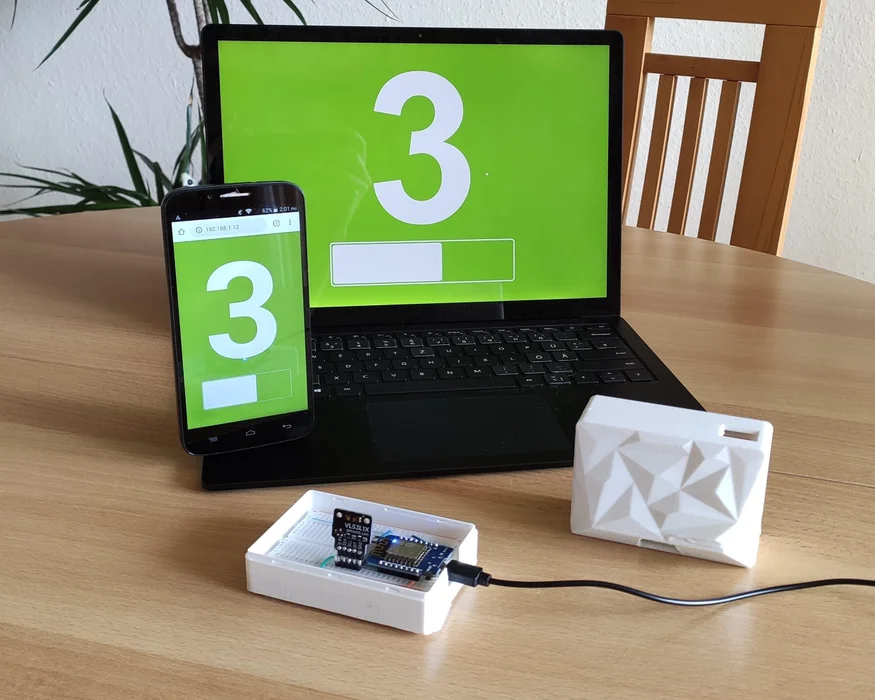
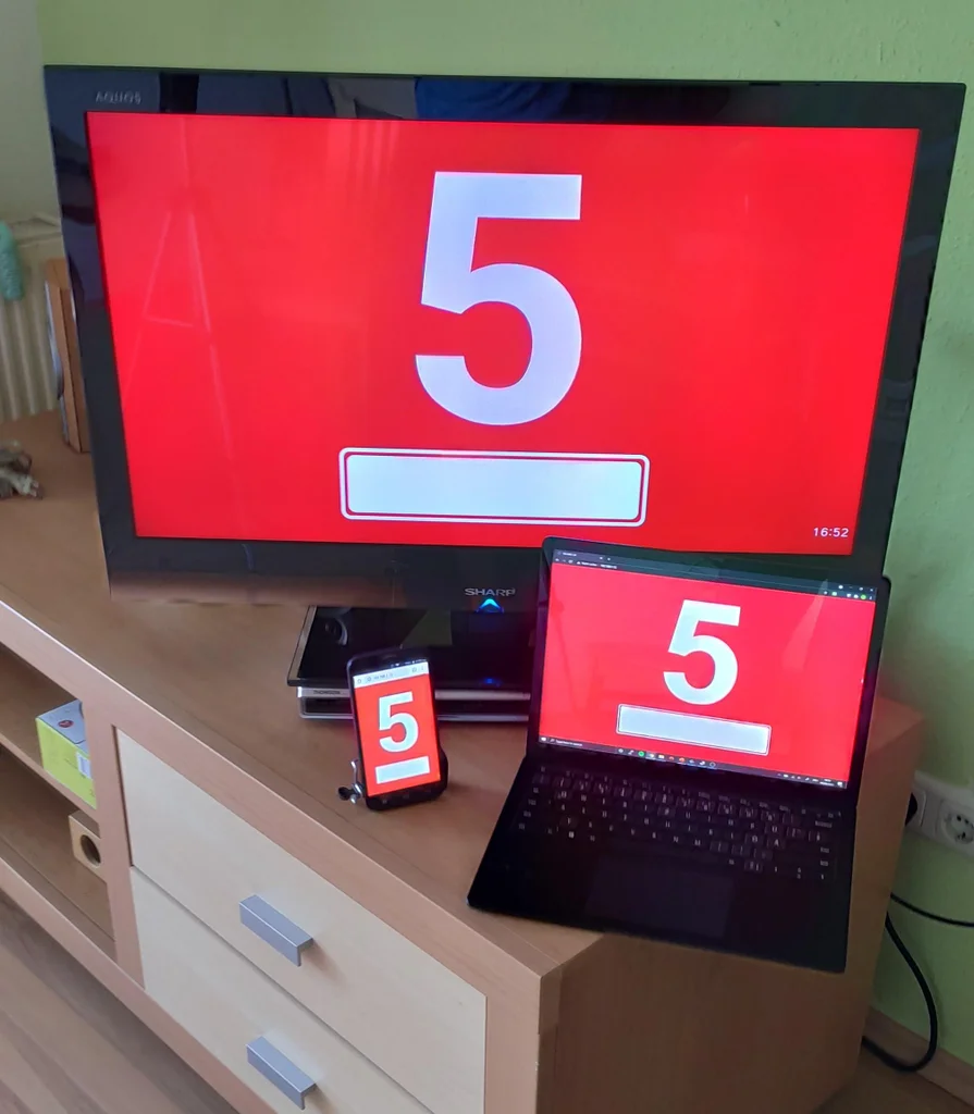
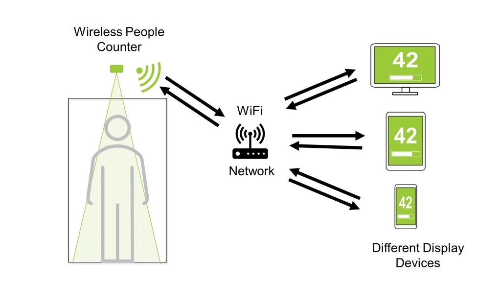
✌️The people counter that I am going to show you today uses a laser to count the people and can be connected to any device that has a webbrowser using WiFi. This allows a simple web UI to be displayed on all kinds of devices as seen in the fifth image. I also attached a little video so you can see it in action.
It is a neat little project, that includes electronics, cool new sensor technology, Arduino programming and even a little bit of 3D printing. And the best part: You can build one yourself for under 20 €.
he backstory?
My people counter journey started way back in 2019, when I was working on an unrelated IoT project. I was using a tiny little distance sensor called the VL53L1X (more on that in step 3) and saw a proof of concept video from ST Microelectronics that showed it being used as a people counter. Fast forward to 2020 and we have a global pandemic. One that requires us to social distance. For stores, restaurants, gyms and all other kinds of enclosed public places this means that it is now necessary to limit the amount of people inside. A job for a people counter. I was just waiting for them to appear in any store in no time but that didn't happen. Here in Germany only a hand full of shops started using electronic people counting systems. The rest placed a person at the store that counts manually.
I was wondering why that is and did a little bit of research. To me it seemed that there were three major reasons:?
- Nobody knows that electronic counters exist
- People Counting Systems are too expensive (Especially with a big display for the customers)
- The systems are complicated and require technicians for installation
I remembered the proof of concept from ST which used a really cheap sensor. The demo was very basic and was missing things like a proper user interface but it looked promising. Could that be a better people counter that addresses the above issues?
Fast forward to today and I spent half a year developing a working prototypes and learned a ton of things about people counters.
Step 1️⃣: What you need✨
to build yourself a simple laser people counter
- WEMOS D1 Mini
- VL53L1X ToF Sensor Module
- Small Breadboard
- Jumper wires
- long Micro USB Cable
- USB Power Brick
- 3D printed enclosure (optional) STL Files in step 5
Tools:?️?
- Soldering iron
- Laptop with Arduino IDE
- 3D Printer (optional)
Step 2️⃣: Theory - How to Count People✨
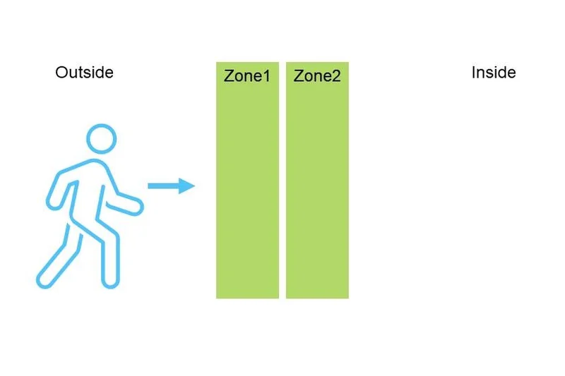


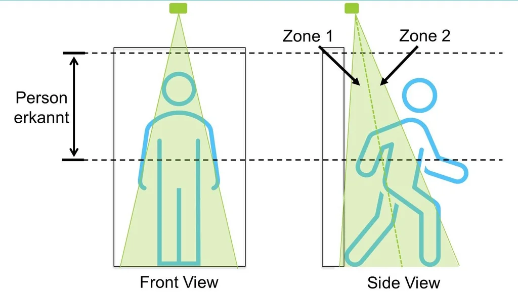
Counting people is not that different from counting objects. We just need to place two detectors in the heading direction of a person as seen in the first image. A detector can be any kind of sensor. For now we just need to know that we have two sensors and that each of them can tell us if a person is present or not. Each sensor checks in a zone, so we have zone 1 and zone 2 that can have a person inside them or not (true or false).
If a person goes from the inside to the outside, our sensors are going to detect it in zone 1, then in zone 2. Once the person has passed our sensors altogether (both sensors return false), we know that someone has entered the room. We then increase our count by one. If this person then decides to leave the room it is going to enter zone 2, then zone 1. If we look at the signals (image 3) you can see that we only need to check for the flanks on entering or leaving the detection zones. The table next to the graph shows all of the possible signal combinations and their counting result. The two lines at the bottom are people that stand in the doorway but then decide to go back so they are neither leaving nor entering (partial entry). I also made a little animation that shows the zone activation when a person enters and leaves the room (attached video).
So that's it, that is how you count people..... well there are some nuances. A simple people counter, such as the one that I am going to show you today, can only count one person at a time. If there were two people , passing our detection area at the same time, our people counter would get confused.
Step 3️⃣: Theory - Conventional People Counters✨

Before we get into the details of how to build our own people counter, lets take a look at the solutions that are available for purchase. I put a couple of them into the image above. There are plenty and they all have their strengths and weaknesses. That's why I wrote you this little overview.
Light Barrier Counter?
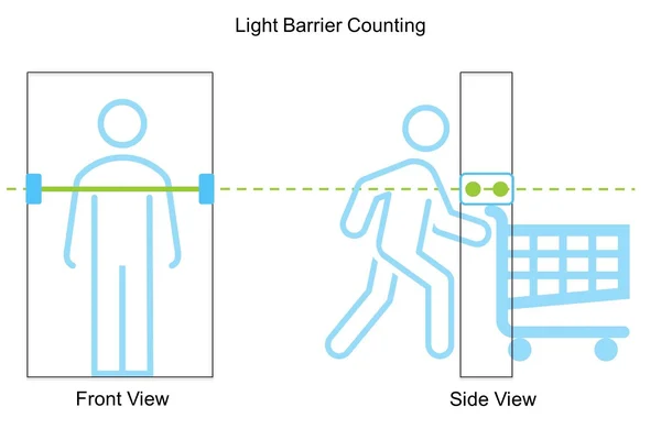
Light barriers are the simplest type of counter. They are mounted to the sides of a door, as seen in the second image. Light barrier counters have two light beams, each with their own light sensor. If a person walks through the light beam it doesn't reach the sensor anymore. Boom, person detected. These types of counters are of the simple type that we discussed in the step before. They can count one person at a time. If there is only one person at a time, they are very reliable and pretty cheap. However the price can quickly increase, if you don't want a big display for the customers as you can see from the first image.
Normal Cameras?
"Normal Cameras" such as the once in your smartphone are the simplest and cheapest way to count multiple people. As mentioned before, counting multiple people is basically counting heads. This is easy if you can clearly distinguish the people from the floor, but that can get tricky if there is bad contrast. Normal cameras are very sensitive to changes in illumination. Those may be caused by sunlight from the outside. It is also very tricky and sometimes impossible, to distinguish a shadow from a person if you can only see a 2D image.
Stereo Cameras?
Stereo cameras are like magic to me. They use two cameras spaced apart similar to your eyes. Through some processing magic this gives you a some depth information so you know what is closer (eg. people) and what is farther away (eg. floor with bad contrast). These are some of the most common people counters, as they are fairly reliable. However they can still struggle with bad lighting conditions.
ToF Cameras (true 3D cameras)?
Time of Flight (more on that later) cameras don't rely on colors or visible light. They also don't need any processing tricks to get depth information. These cameras are true 3D cameras. For every pixel in an image they have a distance. This means that a bunch of people passing below the sensor are seen as a bunch of hills in the 3D image. This technology is very reliable, as it can not be fooled by weird lighting and even works in complete darkness. However, the sensors can be quite expensive and are not that common.
Honorable mentions?
The sensors above are the most common but there is a ton of other sensor types available. Some honorable mentions are thermal imaging people counters, camera counters that use facial recognition (good bye privacy) and sensor mats that are placed on the floor. I won't go into detail about those but they exist.
One thing that is also getting more popular are smartphone counters. They are often referred to as people counters but they are not able to count the exact number of people. They track WiFi and Bluetooth signals and correlate the number of devices that they see with the approximate number of people.
Step 4️⃣: Theory - This People Counter✨
The People Counter, that this Instructable is about, is a little bit different from the ones that are currently available. Mainly because it uses a new Sensor as a people detector.
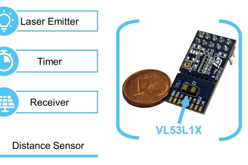
The Sensor?
Our Sensor is called the VL53L1X (seen in the first image), which is a fairly boring and complicated name for a very interesting little sensor. A couple of facts about it:
- It can shoot laser beams (invisible and not harmful)
- It can measure the time it takes light to go to an object and come back
- It is very tiny (4.9 mm x 2.5 mm x 1.56 mm)
- You can use it with any Arduino board
- You can get one for under 10€
- You can split its measuring area
The Time of Flight Principle?
The sensor is essentially a very fast and very precise distance sensor. It uses the so called Time of Flight principle. I tried to visualize it in the second image. The Sensor consists of an emitter that emits a short pulse of laser lights. It waits for the light to bounce of a surface and return to the sensors receiver. Then it checks how long the light took to come back and uses a simple equation to calculate the distance to the object. It is actually very similar to an ultrasonic sensor, which uses the same equation with the speed of sound instead of the speed of light.
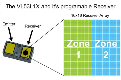
The sensor measures distances inside a cone-like shape (see the third image) with an opening angle of around 27 degrees. This angle is called the Field of View (FOV). However, the sensor does not have to look at the whole cone. The receiver of the VL53L1X is actually an array of 16x16 little light sensors (visualized in the third image). You can use software to tell it to only measure in a certain area of this array. This area is called a Region of Interest (ROI). By using this feature, we can split the cone which gives us two different zones. We can detect a person in each zone by checking if the measured distance is below a certain threshold. And if you read through the second step you already know that we can use this to count people.
Credit where credit is due: I am not the one who came up with this idea. It was the smart folks over at ST Microelectronis, the company that developed and produces the VL53L1X. They implemented a little proof of concept for a people counter back in 2019. You can find their documentation here. I based my people counter design on their concept and gave it a couple of smart upgrades.
Making it Smart?
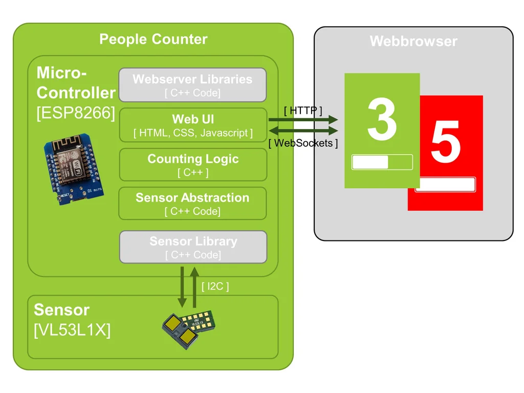
A Sensor that can count people is pretty cool but it is missing a display. We want to display the count on some kind of screen, to make it visible to people entering the store. An easy way of doing this is to use a web-Interface. This allows us to display the count on any device that has a webbrowser, such as a smartphone, a tablet, a laptop or a smart TV. The idea is to connect the sensor and the display device to a WiFi network and have them communicate through that. You can see this concept in the fifth image.
An easy way to create such a "smart" device, that can talk to smartphones, laptops and tvs, is to use a Microcontroller with integrated WiFi capabilities. A microcontroller (MCU) is a little computer that we need to talk to our sensor and do the actual counting. We are going to use the ESP8266 as it can do just that and also includes WiFi and can act as a little webserver, serving websites to other devices. It is also Arduino compatible, which makes it super convenient to program and allows us to use a bunch of great libraries for the sensor and the webserver part.
A More Detailed Look at the software?
Our sensor, our microcontroller and webbrowsers are great pieces of technology, but they will not be counting people if we don't tell them how to do it. Thats why I created a bunch of code. This part is fairly complicated, especially if you are a beginner but I did my best to simplify. The text files that make up my code are pretty boring to look at, that's why I tried to visualize it in the last image.
You can think of it as a stack of software components talking to each other and to certain hardware components. At the bottom we have our VL53L1X sensor. It talks to our microcontroller board through a the so called I2C bus which is just two wires that carry data and signals. Inside the microcontroller is the first software component, a sensor library that takes care of all of the sensor communication. It reduces the bits and bytes going over the bus to simple functions, such as startMeasurement() and getResult(). I put a second layer of code above that. This second layer abstracts all of the specific sensor functions and reduces it further to three simple pieces of information
- is a person in zone 1 ?
- is a person in zone 2 ?
- does the sensor have new data ?
This abstraction opens the possibility of playing around with different sensors. You could replace my ToF-Sensor code with your own code to use two ultrasonic sensors or two light barriers or two switches to detect a person. This way you can build a different kind of people counter but keep all of the user interface code.
The third layer of code implements our people counting algorithm, that we discussed in the second step.
Above all of that, we have the web UI code. If a display device want's to display our count, it uses the HTTP protocol to send a request to the ESP8266 webserver. In the web UI code I define what the people counter should send as a response. I told it to send a simple HTML website. The website also has a little bit of JavaScript that opens a permanent connection to the server, a WebSocket, to update the count whenever something changes.
That is basically it. It was a lot of information but now you know what goes on under the hood of this people counter. Time to build your own.
Step 5️⃣: Making - Assembling the Hardware✨
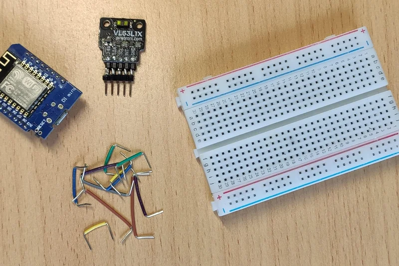
We are going to start with the hardware. This is quite simple, as my design is just a breadboard inside an optional 3D printed enclosure. Considering that, I think that it actually looks pretty good.
Preparing the Boards?
Before you can put your microcontroller board and your sensor board onto the breadboard, you have to solder the pins onto them. These should come with the boards themselves.
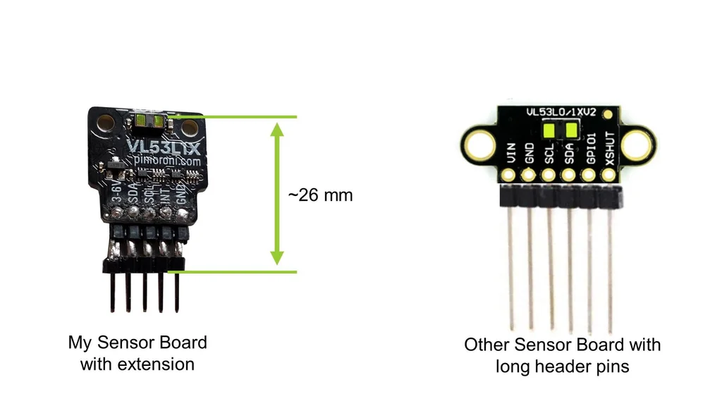
My sensor board was pretty long and I made it even longer by soldering long header pins to it. This way the sensor itself (the tiny chip with the two bronze colored windows) is further away from the breadboard, so that the cone shaped detection zones don't interfere with the wall above the door. If you use a different sensor board, make sure to use long pins or wires to make the sensor sit around 26mm above the breadboard (see image 2).
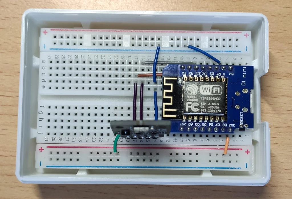
Connecting the Components?
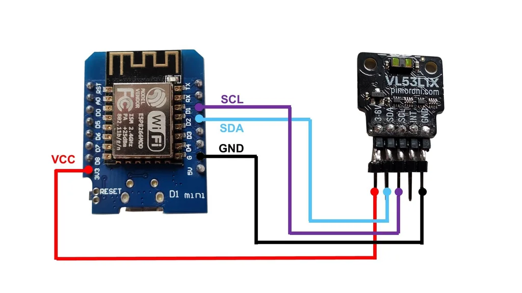
I drew wiring diagram which you can see in the third image. You just need to make the following four connections.
Microcontroller <=> Sensor
- 3V3 <=> VCC
- GND <=> GND
- D1 (GPIO5) <=> SCL D2 (GPIO4) SDA
Use small wires to get clean breadboard connections as seen in the fourth image. Make sure to double, tripple and quadrouple check any connection. Even though this setup is quite simple one wrong connection can turn your fun weekend project into a puff of smoke (I'm talking from experience).
Making an Enclosure?
You don't need an enclosure for our people counter, you could just tape the breadboard to the wall and you'll be good to go. However an enclosure makes it look much more pleasing. I had good experiences in the past with buying cheap lunch boxes and using them as an enclosure.
Since I got a 3D printer I love to make my own enclosures and I also designed one for the people counter that you can download and print yourself. It fits the little breadboard and has a cutout for the sensors detection cone as well as the micro USB cable. It it also has a nice looking low poly front design and the top and bottom pieces are put together by snapping in place.
I printed it in white PLA with 0.2mm layer height, 20% infill on my Anet A8. Make sure to print the top of the enclosure at a 135 degree angle as shown in the last image. This way the low poly surface looks best.
Step 6️⃣: Making - Uploading the Firmware

Once you've got your Hardware ready, it is time to upload the Software also known as the firmware.
Prepare your IDE?
If you have never worked with the Arduino IDE before, you need to take two steps in preparation.
- Download the Arduino IDE here and install it
- Install the Board Packages for the Wemos D1 Mini Board
- In the Arduino IDE go to File->Preferences
- Under Additional Boards Manager URLs paste the following URL: http://arduino.esp8266.com/stable/package_esp8266... and hit OK
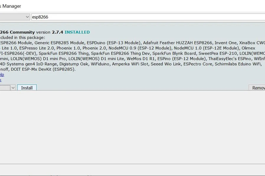
- Go to Tools->Board->Boards Manager
- Search for esp8266 and install the ESP8266 Community Package (image 1)
Now your IDE should be good to go. The next thing you need to do is download my firmware. I put it onto GitHub and you can find it here. Download the whole repository as a ZIP file and unzip it. You can use a free tool such as WinRAR to do this. In the Zip Archive you should find a folder called libraries, which contains the external pieces of software, that we need to talk to the sensor and to use web sockets. Take the contents of this folder and move them to your Arduino IDE's libraries folder. This should be under Documents/Arduino/libraries .
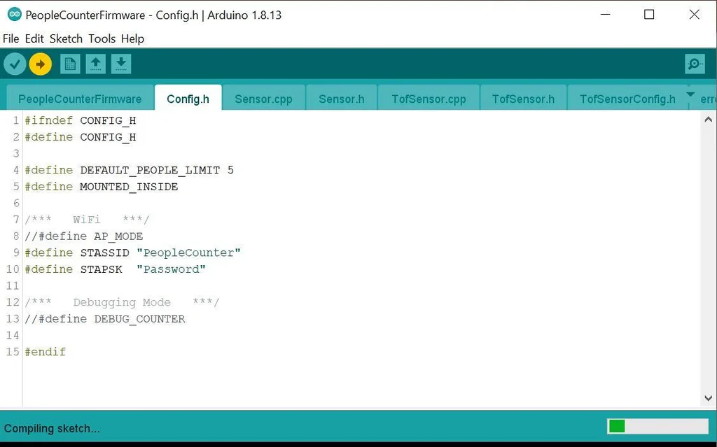
Configure your People Counter?
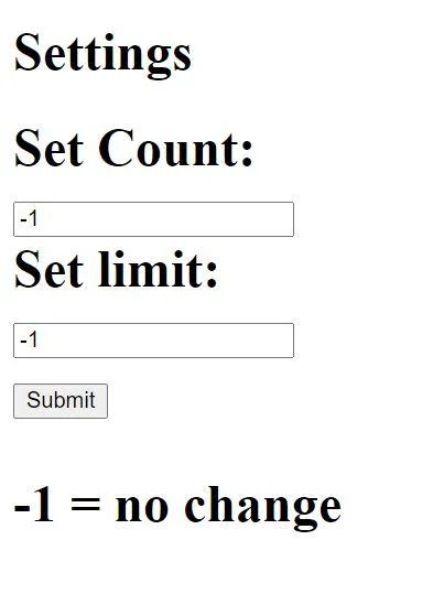
Now open the PeopleCounterFirmware.ino file using the Arduino IDE. You will have to configure your People Counter using the Config file. Open Config.h which contains most of the important parameters. DEFAULT_PEOPLE_LIMIT defines the maximum number of people that should be in the room. This limit is set on startup but can also be altered through a little secondary webpage that the counter hosts under <IpAdress>/correction.
MOUNTED_INSIDE has to be uncommented if your counter counts in the wrong direction.
STASSID and STAPSK have to include the name and password of your local WiFi Network.
Uploading?
Time to upload the firmware to the counter. Plug a Micro USB cable that can transfer Power AND Data into the Micro USB Port of the counter. The other end goes into your PC.
In the Arduino IDE go to Tools->Board->ESP8266 Boards and choose "LOLIN(WEMOS) D1 R2 & mini". Next up chose the correct COM Port through Tools->Port. There might be several different COM ports. To find out which one is the correct one for your People Counter you might have to unplug it and see which Port disappears. Then you reconnect it and choose the new Port. You will have to click on Tools again in order for the ports list to refresh.
Now you can finally compile and upload the firmware using the upload button (second round button in top left corner) and watch as your code is compiled and uploaded to the People Counter.
If the compilation or the upload fails, make sure that you followed all of the above steps correctly. The compiler also trys its best to tell you what went wrong so it might help to take a look at the dialog box at the bottom of the Program.
If you upload the firmware a second time the sensor might stop counting. This is most likely caused by the I2C bus being jammed. As with most it problems, this can be solved by turning it off and on again, aka unplugging and replugging the USB cable.
Step 7️⃣: Making - Connecting and Mounting the Sensor


Connecting to the Sensor?
Before you mount the sensor you should verify that it is working and that you can connect to it. Assuming that you have done anything right in the previous steps you should just have to connect it to a USB power source and the people counter will establish a connection to your specified WiFi network. Next you will have to find it there and get its IP address. There are different ways to do this. You could use the Serial Monitor of the Arduino IDE to see the debugging output of the people counter or you could access your WiFi routers web interface and check which devices are in the network. I like to use a little smartphone app called "network utilities" which allows you to do an IP Scan in your local Network. If your smartphone and the counter are connected to the same WiFi network and your location services are turned on this should bring up an Espressif device (as seen in the first image). This device is your counter.
Copy the IP address, head over to your webbrowser of choice and enter it. It might take a couple of seconds but you should now see the web interface of the sensor (image 2).
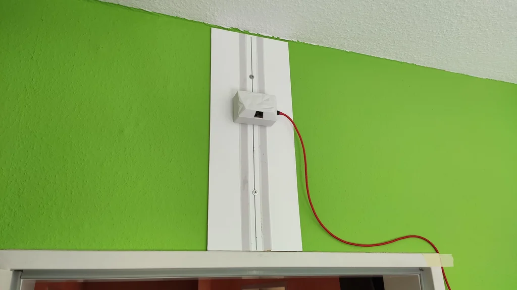
Mounting it above the Door?
The counter has to be placed above an entrance, looking downwards. As the detection zones are cones, they get wider, the further you are from the sensor. For that reason you want to mount the sensor about 30 cm above the door as seen in the fourth image. The sensor currently not differentiate between a door being opened and a person passing by (more on that in the next step) so be sure to mount it on the inside, if your door opens to the outside or the other way around.
After some trial and error I finally found a good way to mount the people counter above my entrance. I glued some velcro to the back of the sensor and the other side to a thin piece of wood. The piece of wood is mounted to the wall using two screws and the counter just sticks to it. As you can see from the images my wooden base plate is pretty long. This allowed me to test the sensor in different mounting heights. You can use a much smaller base plate or mount the sensor straight to the wall. The same mounting style (velcro + base plate) can be used to mount a display device, such as a smartphone, to the wall.
The micro USB cable has to go from the sensor to the next wall outlet where you can plug in the USB power supply. A neat way to route the cable there, without having it dangling into the door area is to use some adhesive mounting hooks such as these.
Test It?
Time to try it out. Access the sensors webpage using your device of choice and walk through the door. You should see the count changing. If it works you are done, you successfully built your own people counter:).
Step 8️⃣: Weak Points
My journey with this counter wasn't always pleasant. As with any project, it has it's downsides and it is important to talk about those. Thanks to the fact, that developing my counter was part of a university project, I had time to take a closer look at the shortcommings of using the VL53L1X as a people counter. I want to use this step to talk about those weak points.
This part gets very technical and you don't have to read through it if you don't want to. None of the sensors flaws are a real dealbreaker but you should know about them so here is a short list:
- It can't differentiate between doors and people (software issue)
- Fast people distort the count (limited sensor speed)
- a single VL53L1X with two measuring zones is very noisy (missing calibration)
My method?
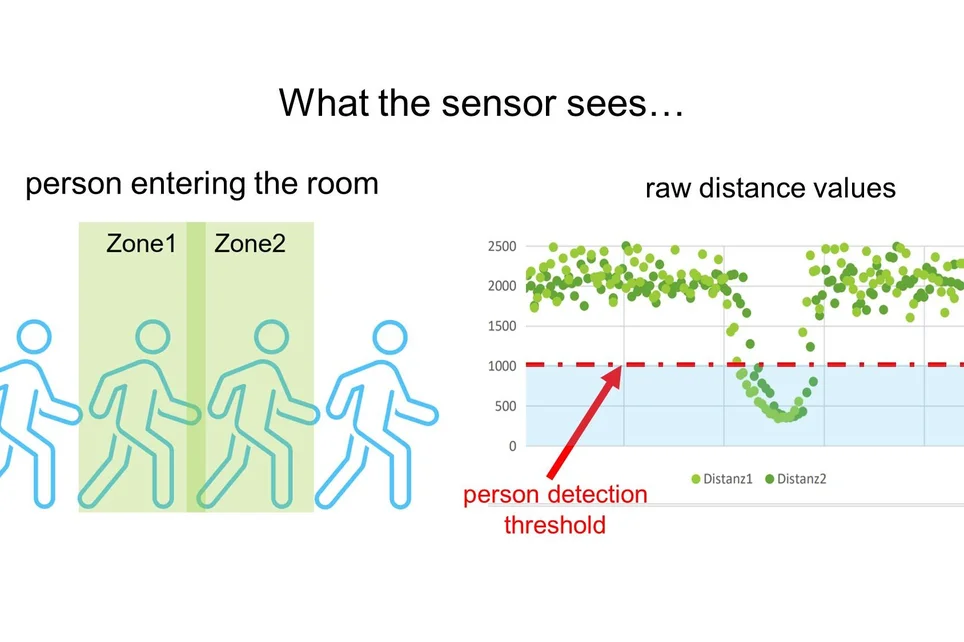
Some of the issues didn't always show up and I didn't really understand why the sensor would sometimes work and sometimes not. I decided to analyze these issues by taking a look at what the sensor sees. So I modified the code to output the distance values of the sensor to the serial monitor of the Arduino IDE. I then copied those values into a .csv-File, opened it in Excel and made a couple of diagrams. The first image shows the result of this. When a person is passing underneath the sensor, we see both green lines (the distances measured in zone1 and zone2) dipping. If they dip below a threshold, we can tell that a person is present.
So far so good.
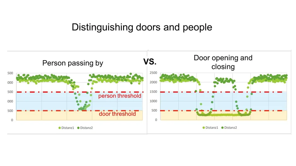
Flaw 1: Doors?
My first thought when designing the sensor was that distinguishing between a person and a door is pretty straight forward. A door is higher than a person. So I could just define two distance thresholds, one for door and one for person, and if the distance is in between the two, we have a person. The raw data showed me that it is not that easy. In the second image we've got the raw data from a person passing by and my door being opened and closed. I also put two threshold lines in and colored the areas in which a person or a door is detected. As you can see, the values don't just jump from zero to person distance or to door distance. They climb to their final distance. That means that a door is briefly detected as a person and counted as a person.
A solution would be to consider a series of multiple distance values and see if the distance stays between the person thresholds or goes above the door threshold. My current Firmware doesn't do that therefore my counter is currently confused by doors. That's why I added a quick and dirty fix: A little webpage that allows you to manually correct the count. It runs on the counter and can be reached by entering /correction in your browser. You can also just not place the sensor above a door ;D.
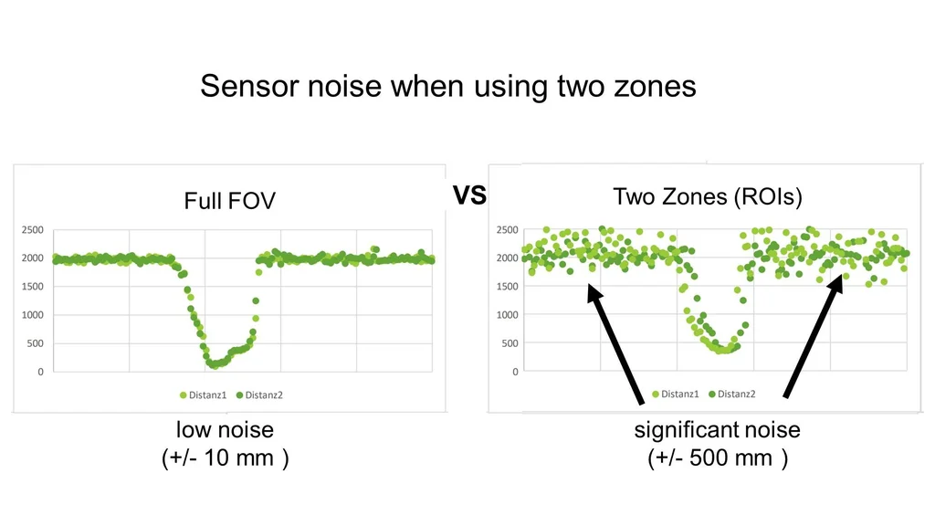
Flaw 2: Sensor Noise?
Another issue that the raw data revealed is that our little ToF Sensor can become pretty noisy. The fourth image shows what I mean. If we use the sensor "normally", meaning that we use all of it's pixels and don't set any zones, we very accurate distance readings and nice smooth curves. If the sensor is switched to ROI mode it just goes all over the place. There is a lot of noise. This noise can cause the distance reading to sporadically go into the detection range for a person and leave it again (very frustrating to debug :D). This makes differentiating doors from people even harder.
There is two solutions for this, which I haven't yet looked into.
- Calibrating the Sensor - The VL53L1X can be calibrated for the ROI of every Zone. The calibration data can be uploaded to the sensor and should increase the accuracy. However I am not sure how well this works if we constantly have to switch between two sets of calibration data to use two different zones.
- Using two VL53L1X - simply going from one sensor with two Zones two two sensors (one for each zone) is probably the easiest fix to get hight accuracy in both zones. It would also make the measurement faster, as we could check both zones at the same time.
Flaw 3: Fast People?
If you are very fast, the sensor wont detect you. It takes a little bit of time to measure the distance in a zone. I measured around 60 ms to check both zones. Lets say the detection area of one Zone is around 50 cm long. The sensor has to check the zone at least once while the person is in it. If the person is standing at the border of the zone, the sensor does not really recognize it. Therefore the effective zone length is reduced even further. Let's say we have 60 ms in which the person can only move 25 cm. This gives us a maximum speed of around 4m/s or around 14km/h. In practice I have found that if I run through the door, the counter does not always recognize me. This might be a problem in some applications that can be solved by using two VL53L1X as stated above.
Step 9️⃣: Final Thoughts

You made it all the way to the end. You now know how to build a simple people counter.
Time for some final thoughts:
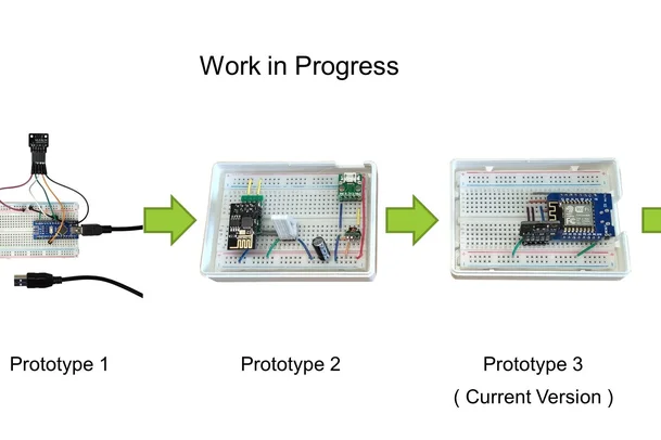
My design came a long way from the first prototype (seen in the image 1). Although the sensor has some quirks, as I discussed in the step before, it does it's job. I think that building this people counter is a great project for any hobbyist or student and it can be used to prevent overcrowding in small stores and restaurants.
Possible Future Version?
As with any new thing that I built from scratch, I already want to build a newer and better version. So let's play a little whishing game. What would I do, if I had a ton of time, material and motivation to build another iteration of this counter ?
First of all I would finally move to a proper printed circuit board. The second image shows you what this could look like. As there are not that many components, it could become as small as a credit card. This form factor would allow the counter to either be mounted to the wall above the door or straight to the ceiling, while it would still be looking downwards. I would also move on to using two VL53L1X sensors. This would allow me to check two Zones simultaneously and probably solve some of the issues described in the step before.
Most of the changes would appear on the software side of things. I would add a setup page, so you could configure the sensor without having to hard code everything. This future counter should also be able to log the counting data and have a little stats page. This would allow a store owner to know how many people visited the store in a day or a week and give it many more uses, apart from preventing too many people from entering. It would also be very useful to develop a way to use multiple sensors for rooms that have multiple doors.
A Couple of Last Words?
As I don't have unlimited time on my hand and my little people counter works well, I am going to leave it as it is and finally share it with you and all of the other creative people in the world.
I hope I could inspire you to build your own people counter. Maybe I even inspired you to pick up where I left off improve my design.
In any case, I hope you enjoyed this Instructable and am looking forward to heating your feedback. I am also open for questions and further improvement ideas.
Thank you for reading and have a great day :)
PS: If you think this is a great Arduino Project, you might want to vote for it in the Arduino Contest.
Special note: The author of the above article is Basement Engineering , Original shared link:https://www.instructables.com/DIY-Laser-People-Counter/???