

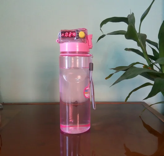
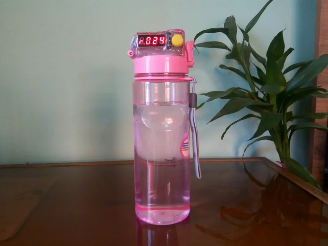
DIY Project——Arduino Powered Water Bottle

Drinking enough water is very important for our health. Drinking more water can lead to clearer skin, better overall health, improved productivity and brain function, increased energy levels, and even weight loss.
?In our busy life it is really hard to remember to drink enough water and most of the time we forget to drink enough water either we are in home, office or on the go. Around 75% of Americans are chronically dehydrated all the time.
?So, in order to build a healthy water drinking habit, it’s important to track your water intake every day.
?To track my water intake I made my water bottle smart using Arduino.
It can:
✅1. Track my daily water intake
✅2. Track my weekly average water intake
✅3. Remind me to take water
✅4. Track last intake time
✅5. Run more than one month in a single charge.
?Demo Video:
Step 1️⃣: Bill of Materials✨
1. Waterproof Ultrasonic Sensor
2. Arduino Pro Mini
3. RTC Module
I made the RTC module myself using DS1307 RTC and 32.768 kHz crystal. In next step I will show you how I made the RTC module.
4. Common-cathode 4-digit 7-segment Display
5. Piezoelectric speaker
6. Momentary Pushbutton Switch - 12mm Square
7. Transistor - NPN (2N3904 or 2N2222 or any compliment) (4 pcs)
8. Li-ion battery charger Module
9. Polymer Lithium Ion Battery - 400mAh
10. Your water bottle (unsmart one, we will make it smart.)
11. Resistors (8 x 220 ohm, 2 x 4.7k, 4 x 1k)
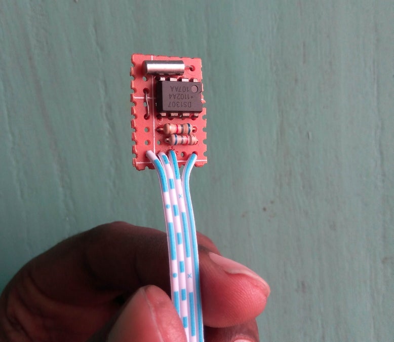
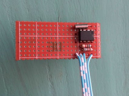
Step 2️⃣: Making RTC Module✨
To log or track water intake information its require current time and date information to be stored along with the accumulated data. A Real Time Clock (RTC) chip such as DS1307 with a suitable back-up battery can be used to supply the required information. The programming process of the RTC chip (in software) is also very simple and is supported in the majority of programming environments.
Here is the design of a compact RTC module, based on the popular RTC IC DS1307, for your everyday microcontroller projects. The DS1307 serial real-time clock (RTC) is a low power, full binary coded decimal (BCD) clock/calendar plus 56 bytes of NV SRAM. Address and data are transferred serially through an I2C, bidirectional bus. The 24-hour/12-hour format clock/calendar provides seconds, minutes, hours, day, date, month, and year information, including corrections for leap year.
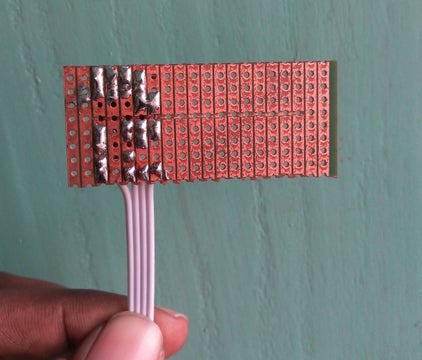
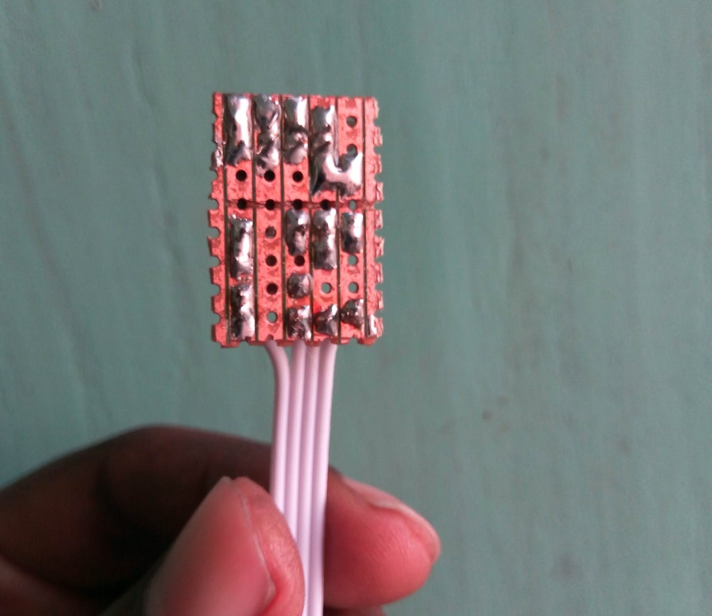
Let's make the real time clock module according to the attached schematic. DS1307 RTC requires an external crystal to operate correctly. Two pull-up resistors are required for SCL & SDA pin of the IC. The value of the resistor may be around 2k to 10k . I used 4.7k. During soldering I tried to keep the module as small as possible because space is limited for my circuit. You can use DS3231 instead of DS1307 and the IC has an internal crystal oscillator. So, you need not to add any external crystal. You may also buy a ready-made tiny RTC module if you don't like to make it own. As the complete system will be operate from battery, for the reason I connected VBAT pin of the RTC to ground without using coin cell.
Important Pins of DS1307?:
5V Pin: When this pin is high then the ds1307 sends the data and when it is low it runs on the backup button cell.
GND: This is the ground pin for the module. Both the ground of the battery and the power supply are tied together.
SCL: It is the i2c clock pin - Which communicates with the microcontroller. Should connect with arduino SCL pin.
SDA: It is the i2c data pin - Which communicates with the microcontroller. Should connect with arduino SDA pin.
VBAT: Battery input for any standard 3V lithium cell or other energy source. Must be grounded if not used.
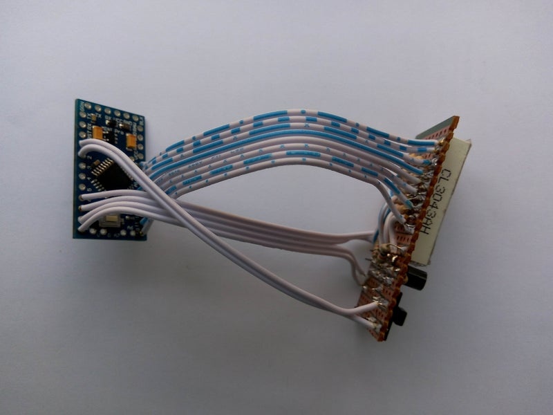
Step 3️⃣: Making Seven Segment Display Board✨
For the display module here I used a self-contained, compact common-cathode module containing four 7-segment LED numeric displays good for displaying numerical data with some simple character.
Each segment in the display module is multiplexed, meaning it shares the same anode connection points. And each of the four digits in the module have their own common cathode connection point. This allows each digit to be turned on or off independently. Also, this multiplexing technique turns the massive amount of microcontroller pins necessary to control a display into just eleven or twelve (in place of thirty-two)!
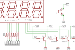
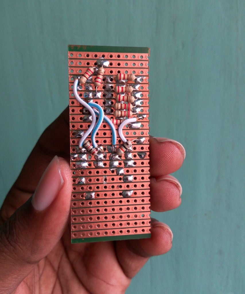
The LED segments of the display require current-limiting resistors when powered from a 5 V logic pin. The value of the resistor is typically between 330 and 470 ohms for 5 V. For li-ion battery operation it may be 220 ohms. And, driver transistors are recommended to provide additional driving current to the LED segments, because each pin of a microcontroller can source or sink near 40 mA of current only. When all (seven) segments of the display turned on at once (the numeral 8), the current demand will exceed this 40 mA limit. The image shown below indicates the basic wiring diagram of the current limiting resistors and driver transistors.
This 4 -digit 7-segment display section is wired around four common-cathode 7-segment LED displays, and four 2N2222 npn transistors. The 1K resistors are used for base current limiting, and the 220R resistors limits the operating current of the LED display segments.
In the Arduino board, digital outputs from D10 to D17 are used to drive segments (a to g & dp), and digital outputs D6 to D9 are used for the digits (D0-D3) of the 4×7 LED display.
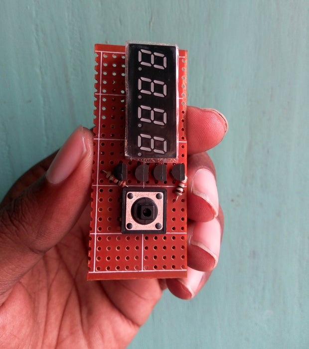
A button switch is added with the display module to access different options. It will also used to wake up the arduino from sleep mode using external hardware interrupt. so, button is connected to arduino digital pin #2 (INT0).
Step 4️⃣: Preparing Ultrasonic Sensor and Buzzer✨
The principle of operation of the ultrasonic sensor system is to use the ultrasonic pulses which are transmitted by the transducer to the surface to be monitored and are reflected back to the transducer, the time period between transmission and reception of the sound pulses is directly proportional to the distance between the transducer and surface, A micro-controller computes this time period for all echoes received and analyses them to determine which is the correct reflection from the material surface, it uses this data as the basis for giving control outputs and displays in usable engineering units. The distance D is determined from the velocity of sound and the time period t by the formula: D = .t /2.
Example: With the velocity of sound = 334.1 M/s, a time period of 60m/s corresponds to a transmission path of 20.046M and thus to a distance of 10.023M.
Ultrasonic pulse will bounce from liquid level since because change of density of ultrasonic pulse travel medium (ultrasonic pulse first travel through air and bounce of liquid with higher density than air). Because water has higher density, majority of pulse will bounce off.
Though it is a contact less methods is to measure distance between transceiver and fluid there are two disadvantages exist with ultrasonic method:
1st: because of pulse length there is small window that we cannot receive pulse with transceiver because transceiver is transmitting. This problem is simple to solve: we placed our sensor higher from maximum water level for few centimeters allowing receiver to start receiving.
2nd: because of the beam width we are limited with bottle diameter. If bottle diameter is too small, signal could bounce of bottle’s walls and could cause false readings.
To know more details about it please read this nice instructable: Measuring water level with ultrasonic sensor by vonPongrac.
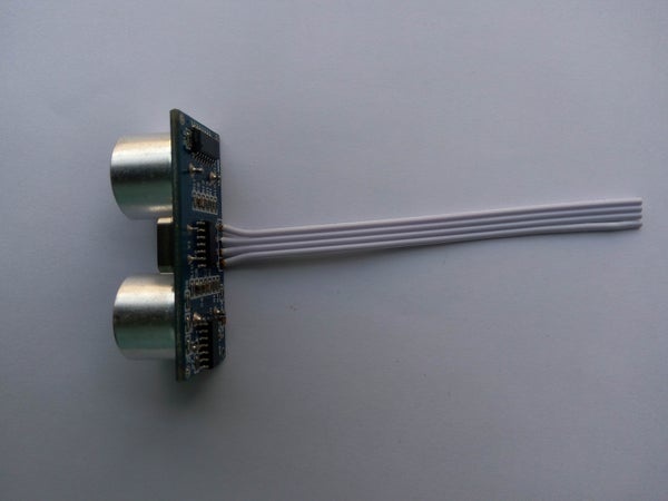
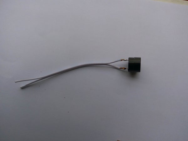
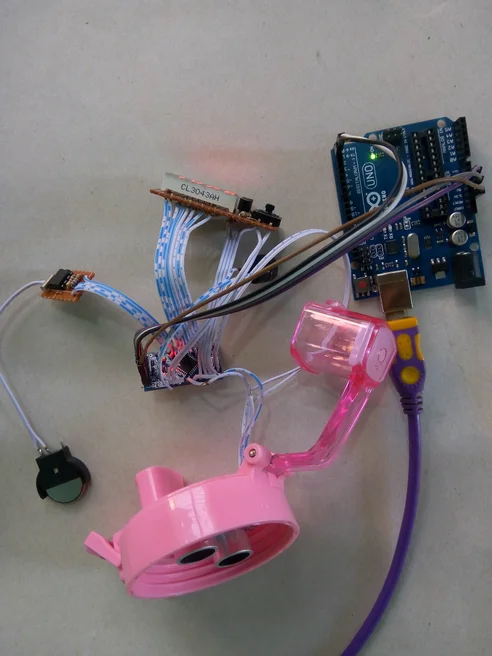
Lots of theory. Now, solder 5 CM long jumper wire with the ultrasonic sensor and buzzer as shown in the image. You will connect trigger pin of the sonar to Arduino digital pin #4 and echo pin of the sonar to arduino digital pin #5. Buzzer pin should be connected to arduino digital pin #3.
Step 5️⃣: Connecting Display Board With Arduino Mini Pro✨
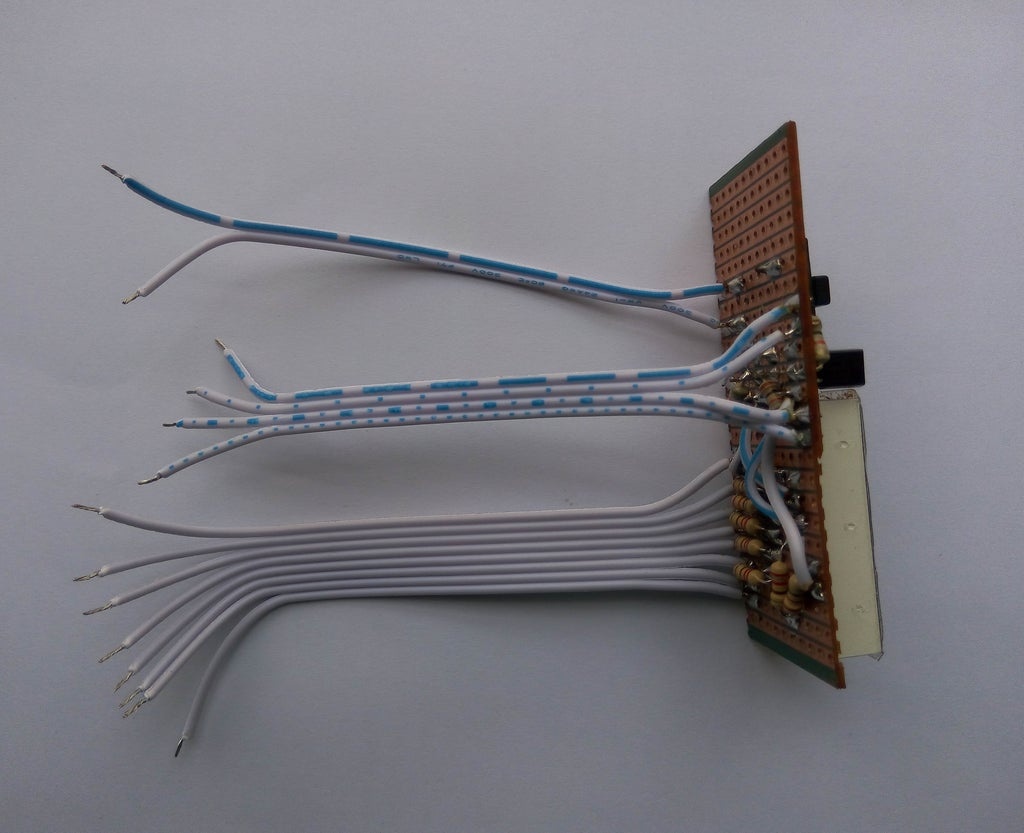
According to the schematic provided before solder all the segments pin to the arduino mini pin. Then solder 4 common pin to the collector pin of the transistor. Transistor's bases are connected to arduino pin. After connecting the display connect the button switch with the arduino digital pin 2 (INT 0). Be sure you connected button to arduino pin 2 because we will implement external hardware interrupt to wake up arduino from sleep mode using this button.
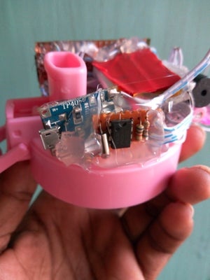
Step 6️⃣: Connecting RTC Module and Buzzer✨
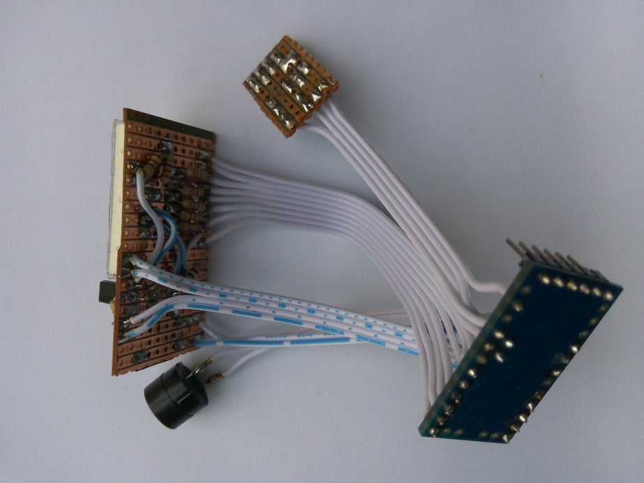
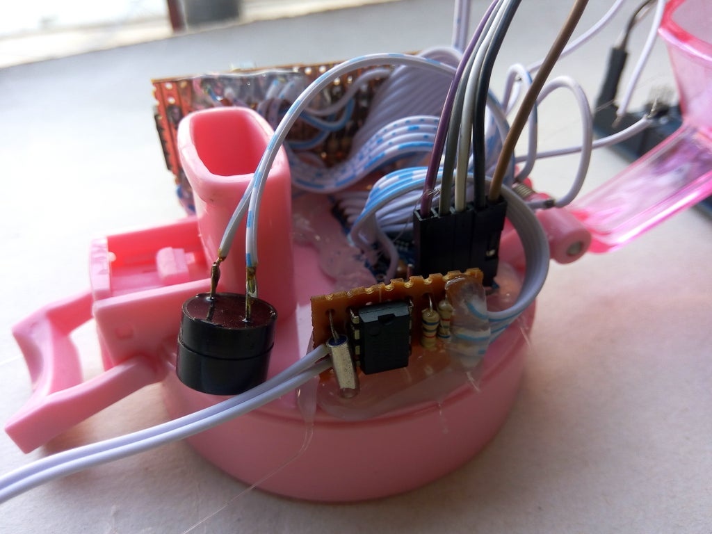
Now, connect the RTC module you made earlier to the arduino board. SDA pin of the module must be connected to SDA (A4) pin of the arduino pin and SCL pin of the module must be connected to SCL (A5) pin of the arduino. Then connect the buzzer to the arduino board.
✨Connection:
RTCArduino ------> Mini Pro
SDA ------> A4
SCL ------> A5
Buzzer ------> D3
Step7️⃣: Attaching Ultrasonic Sensor With Bottle Cap✨
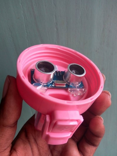
Make a hole into the bottle cap as shown in the image. Bring out four wires of the ultrasonic sensor through the hole and fixed the ultrasonic sensor at the middle of the bottle cap. Sensor must be attached in the inner side of the bottle cap and it should be place at the center position.
✨Connection:
Ultrasonic Sensor ------> Arduino Mini Pro
VCC ------> VCC
GND ------> GND
Trigger ------> D4
Echo ------> D5
Step 8️⃣: Uploading Program & Testing✨
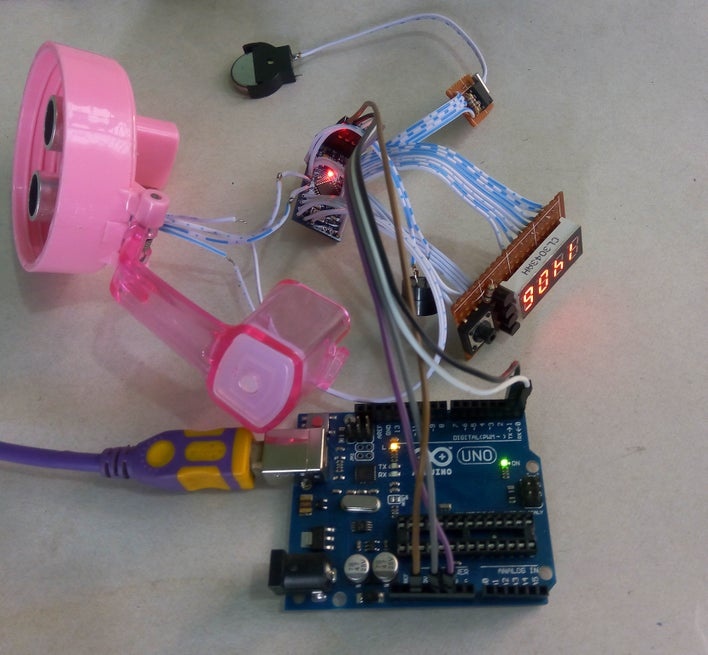
?After completing all the connection it is the right time for uploading program to Arduino board and testing the functionality. You will be required several library for the program to work correctly. For button interfacing you need to add OneButton library. As the device will operate from battery, power consumption is an important issue. I implemented sleep mode to my arduino sketch. Watchdog timer and external hardware interrupt was used to wake up the Arduino from sleep mode. Arduino takes sensor reading for three times, average it and calculate the necessary information and display information for 10 seconds and then go to the sleep mode for 1 minutes. It wake up any time on button pressed connected to INT0 (digital pin 2). So, if you want to see the information about your water intake just press the option button any time. It will wake up for you. Without any button press it will take reading every 1 minutes. For implementing sleep mode I used arduino Low-Power library. For reading time from DS1307 RTC module I used DS1307RTC library. So, for compiling the attached program add all the library to your environment.
I will explain here only the calculation algorithm in brief. See the attached fill for complete sketch. Calculation is done from the average of five sensor readings to make it accurate enough. Daily reading is reset at 24 hours and prepared for new reading for new day.
无效计算(){
  float water_level = 0;// 存储每一步的水位
  int read_value = 0; //以cm为单位读取传感器读数

  for(int i=0; i<5; i++){ //取五读
      read_value = distance_in_cm();
      if(read_value>16 || read_value<3){// 读数不稳定
          返回; //返回调用函数,因为读取不稳定
        }
      else if(read_value<=16 && read_value>=3){//有效值
          water_level = water_level + read_value;
        }
      延迟(10);
   }
  average_water_level = 17 - water_level/5; //从五个读数中找到平均值,17 = botole高度
  water_amount_in_ounce = int(average_water_level*1.87);//16厘米水位=30盎司
  if(water_intake_times==0){
     previous_water_amount = water_amount_in_ounce;
     water_intake_times = 1;
    }
  if((water_amount_in_ounce < previous_water_amount-1) && (hours < 24)){//消耗了一些水
    water_intake_ounch[water_intake_times - 1] = previous_water_amount - water_amount_in_ounce;
    water_intake_times++;
    previous_water_amount = water_amount_in_ounce;
    }
  else if(water_amount_in_ounce > previous_water_amount){ //重新加水
    //这里补水
    previous_water_amount = water_amount_in_ounce;
    }
  else if(water_amount_in_ounce == previous_water_amount){ //没有水消耗或重新填充
    空闲时间+=1;
    }
  if(hours==23 && minutes==59){ // 一天结束,新一天的所有值都从零开始
    for(int i=0; i<15; i++){
      water_intake_ounch[i] = 0;
      }
    water_intake_times = 0;
    摄入_天++;
    if(intake_day==8){
      摄入_天= 1;
      }
    }
}
int total_water_intake_in_day(){//计算一天的总饮水量
  total_water_intake_today = 0;
  for(int i=0; i<water_intake_times; i++){
    total_water_intake_today = total_water_intake_today + water_intake_ounch[i];
    }
    water_intake_days[intake_day] = total_water_intake_today;
    返回 total_water_intake_today;
  }

int average_water_intake_last_week(){//计算上周平均饮水量
  for(int i=1; i<=intake_day; i++){
    average_intake_last_week = average_intake_last_week + water_intake_days[i-1];
    }
  average_intake_last_week = average_intake_last_week/intake_day;
  返回average_intake_last_week;
  }
Average water intake is prepared from the average of previous seven day's daily intake. You 2 hours passed without intake of any water it will alert the user with double beep in every 15 minutes and stops for next 2 hours after intaking water.
Download the attached code and upload it to your Arduino mini pro. Connect all the module and power it up to test either all components is working correctly or not.
If display shows some result then Congratulation!!! You already done the hard things.
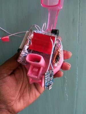
Step 9️⃣: Fixing Arduino With Bottle Cap✨
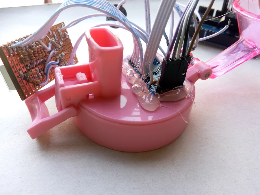
Using hot glue attache arduino mini to the upper side of the bottle cap. Keep in mind that you have to fix all the component into the bottle cap. Add enough glue so that it tightly attached to the bottle cap.
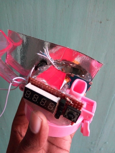
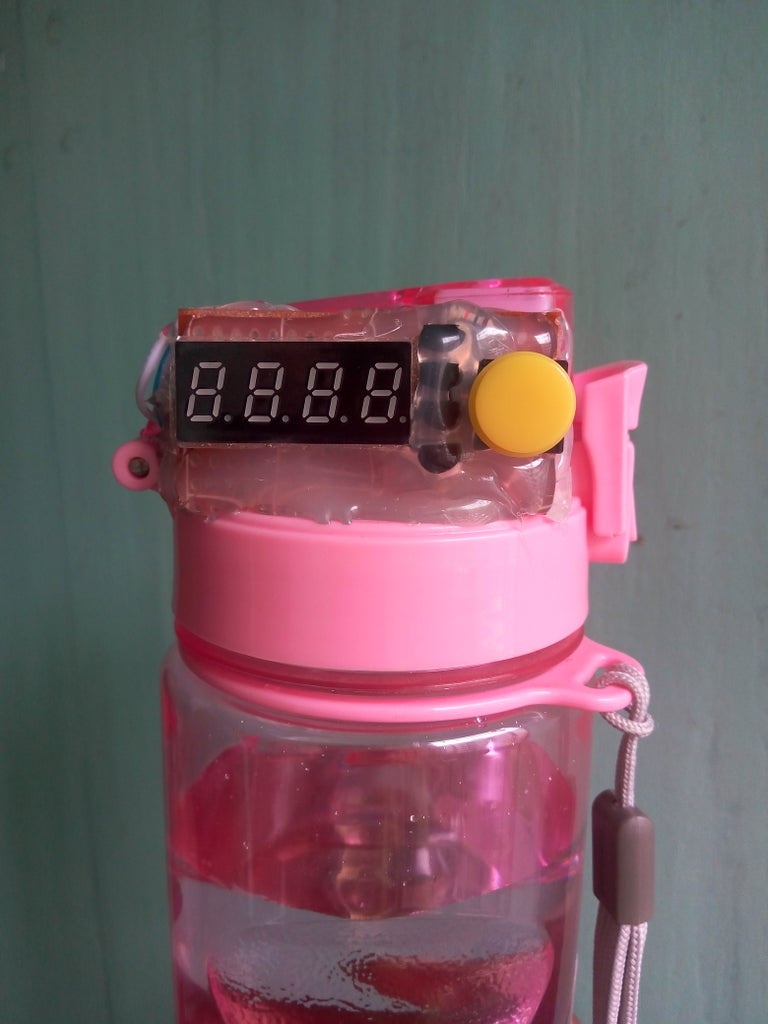
Step ?: Glueing Display Board With Bottle Cap✨
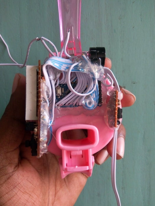

After attaching arduino board it is the time to attache display board to the bottle cap. Keep the display outer side so that it can be easily visible to the user. In the other side attache RTC module tightly with enough glue. You may follow the photos attached in the step.
Step 1️⃣1️⃣: Attaching Battery and Charger Module✨
Now, fix the li-ion battery in the top of the arduino. Be careful about shorting the battery with any open pin. Then connect the charger module with the cap. Keep the usb port easy accessible from the outer side so that it can be connect easily to the charger.
Step 1️⃣2️⃣: Making All the Circuits Waterproof✨
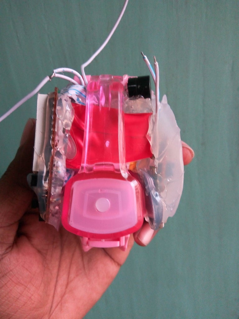
After connecting all the components and module it it the right time to make our device completely water proof. It is very important because it is water bottle and any time water can be drop to the circuit and may damaged the circuit. To make it completely waterproof add enough glue in every outer part of the circuits without the usb port. You can make the cap nice using glue to make it round at original cap.
Don't sink the bottle cap in the water.
Step 1️⃣3️⃣: Enjoy It✨
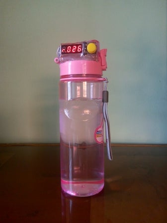
?Congratulation!!! You made it. Enjoy it and modify it in more creative and useful way.
Special note: The author of the above article is taifur , Original shared link:https://www.instructables.com/Arduino-Powered-Water-Bottle/???