

DIY Automatic Plant Watering System

When you hear the term ‘smart garden’, one of the things that comes to your mind is a system that measures soil moisture and irrigates your plants automatically. With this type of system, you can water your plants only when needed and avoid over-watering or under-watering.
This project shows how to make an Arduino based automatic plant watering system. In fact, the idea of making an automatic plant watering system came up with the thought that my plants would be waterless before I went on summer vacation. The soil moisture sensor, water pump motor and some pipe in my workshop came to mind and I wanted to make project.
Take a look at how it works, I think it's been a useful project for your plants or at least give you some ideas. The project is based on Arduino microcontroller. Only, as can be seen in the video, I used a microcontroller prototype that I designed myself. Of course, you can use all other Arduino models in this project. So why did I need a special board? I've explained that in the next step.
Step 2: The Working Principle of the Automatic Plant Watering System✍️
First, let's look at the working principle to understand the requirements of the automatic plant watering system. The plant needs water as the soil dries, and we need to somehow get the water together with the plant soil. If the plant soil is sufficiently watered, we should stop watering. So what hardware or components do we need to do this automatically?
A soil moisture sensor probe should measure the soil moisture, the data read by the probe is sent to a microcontroller via the soil moisture sensor. The microcontroller processes the read data according to the specified commands (like threshold value) and communicates with a motor driver to start the water pump motor. However, in some projects a relay can be used to trigger the motor. The motor driver runs the water pump motor and water flow is through the pipes connected to the water pump motor. When the soil moisture sensor probe reaches the specified threshold, the system returns to the beginning and the water flow is stopped. This is executed as a loop by the microcontroller.
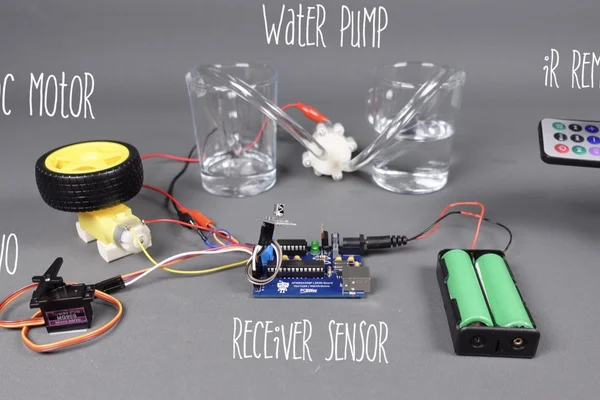
Then the list of components and hardware that we will mainly need is as follows:
- Your Plants
- Soil Moisture Sensor: https://bit.ly/3xMRl7R - https://amzn.to/3jVZfqO
- Microcontroller
- Motor Driver
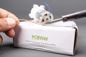
- Water Pump Motor:
- Pipe
- Some Jumper Wires for Connections
- Water Bucket
- Power Supply
Step 3: Which Microcontroller and Motor Driver?✍️
As I mentioned before, you can use any model of Arduino microcontroller (such as UNO, Nano, Mega). As long as the connections are made correctly, the shared source code will run smoothly.
However, if I was going to use an Arduino microcontroller, I would also need a motor driver or maybe even a relay. If we used a model like an Arduino UNO in the project, we would have to create a circuit using the following motor drivers together:
- L293D Motor Driver Shield (It makes it difficult to connect extra sensors)
- L293D Motor Driver IC Chip (It needs a breadboard and needs complex wiring)
- L298N Motor Driver Module (It needs extra wiring)
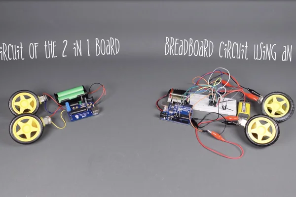
If you are going to use an Arduino model, the circuit can be a bit complicated. To avoid this complexity, I created a prototype and got PCB printing service from PCBWay. On my design board I used an ATmega328P, an L293D motor driver, a CH341 chip to program it easily via USB.
In addition, you can use this board in your different projects another from the plant watering system. For example, this board allows you to control Servo motor, 2 DC motors and many sensors. I used this board again for the 5 in 1 robot project and I created a robot tank that works in 5 different modes with 1 board. If you want to browse, the project link is below:
5 in 1 Robot - https://youtu.be/663y37vYbRM
If you do not want to deal with complex circuits, you can easily get this PCB I designed from the link below. You can get high quality and low budget PCB service from PCBWay.
Get the PCB - https://www.pcbway.com/project/shareproject/Automatic_plant_watering_system
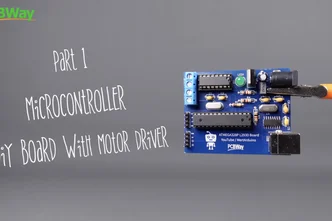
Step 4: 2 in 1 Microcontroller (built-in Motor Driver)✍️
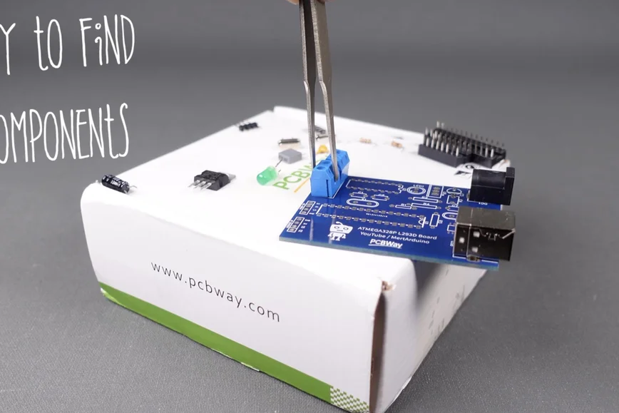
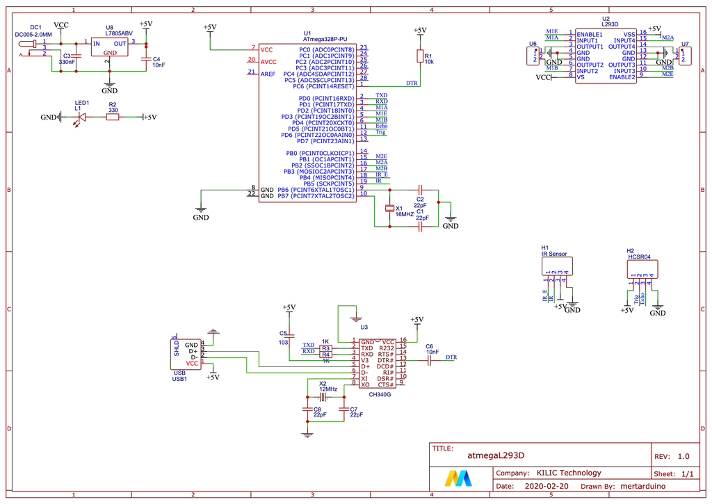
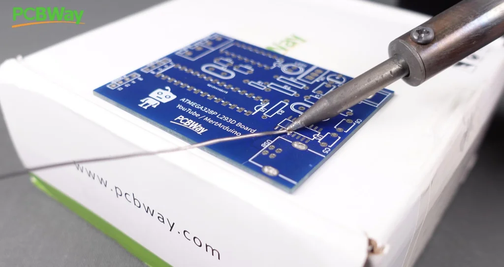
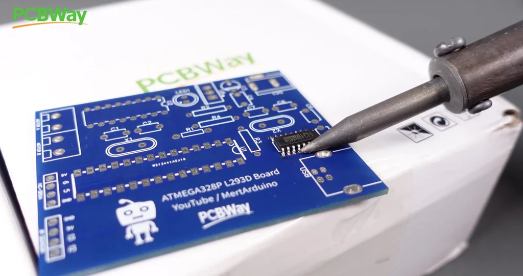
While designing the PCB prototype, I took care to choose components that are easy to find and solderable. On my design board I used an ATmega328P, an L293D motor driver, a CH341 chip to program it easily via USB. Only, the CH341 USB chip may seem a bit difficult to solder. But using a simple soldering iron, drop a small amount of solder on the pads on the PCB where the chip will be mounted, then align the chip legs correctly and heat the chip legs with solder. You can check out the project video for this process.
In addition, you can use this board in your different projects another from the plant watering system. For example, this board allows you to control Servo motor, 2 DC motors and many sensors.
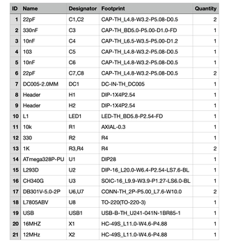
You can get the necessary components from the links below. You can use the designator table I shared for the positions of the components on the PCB.
Required Components
ATmega328P with Bootloader: https://bit.ly/2U9iwJw - https://amzn.to/39sAs9g
L293D Motor Driver IC: https://bit.ly/33BV2ju - https://amzn.to/2ZqRob1
Type B USB Socket: https://bit.ly/2WBSQqw - https://amzn.to/3drUYIl
DIP Socket 28/16 Pins: https://bit.ly/2UahQDK - https://amzn.to/3dqOPMF
12/16 MHz Crystal: https://bit.ly/33FNTyL - https://amzn.to/31yAYhB
L7805 TO-220: http://bit.ly/2N5WnYG - https://amzn.to/3rFGY2A
100uF Capacitor: https://bit.ly/2U98JTU - https://amzn.to/3sFBDcX
Resistor 10K / 1K: https://bit.ly/2WFsNPl - https://amzn.to/3bj2HY9
470nF Capacitor: https://bit.ly/2UwQ2bw - https://amzn.to/3fBj9a4
Power Jack Socket: http://bit.ly/2QAzFdp - https://amzn.to/31G7Mp3
2 Pin Terminal Block: http://bit.ly/2lEgy58 - https://amzn.to/31ETYei
Male Pin Header: https://bit.ly/3ab5h0w - https://amzn.to/3dmwTT9
10nF / 22pF Ceramic: https://bit.ly/2WCuQ6Y - https://amzn.to/31DVAVF
Required Tools
Soldering Station: https://bit.ly/3yjXCsu - https://amzn.to/3jH1ZKf
Soldering Iron Wire: https://bit.ly/3xOs7X0 - https://amzn.to/3xQXAaK
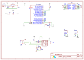
PCB Details
Board type : Single
PCB Size : 53.3mm x 66mm
Layers : 2 Layers
Get the PCB Gerber & Schematic: https://www.pcbway.com/project/shareproject
Step 5: Programming (Source Code)✍️

Before proceeding to the circuit connections step, I recommend that you upload the source code. Because, if you connect your computer via USB to program the board while the water pump motor is connected to the circuit, your computer may be damaged.
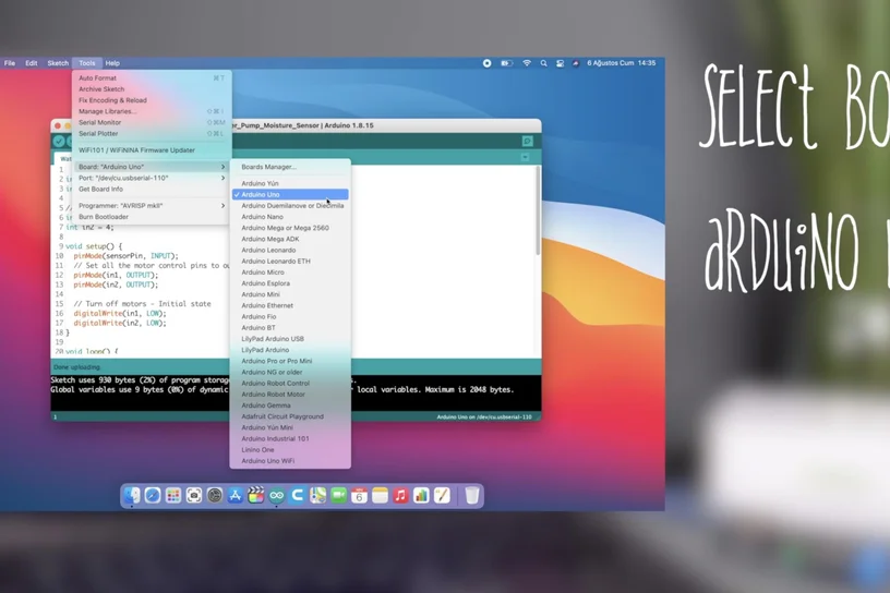
Use any Arduino model or the 2 in 1 board I designed, the source code is compatible with both. When uploading the code, the BOARD selection for the 2-in-1 board should be Arduino UNO. If you are using any of the other Arduino models (such as UNO, Nano, Mega), you should choose the board according to the model you use. You will need to download and use the Arduino IDE editor to open and upload the code https://www.arduino.cc/en/software
Get the Source Code:https://create.arduino.cc/editor/mertarduinotech
Step 6: Connections - Soil Moisture Sensor✍️
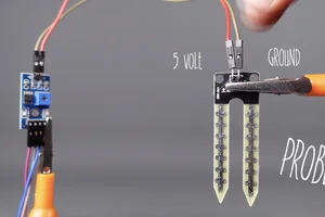
How Soil Moisture Sensor works? The working of the soil moisture sensor is pretty straightforward.
The fork-shaped probe with two exposed conductors, acts as a variable resistor (just like a potentiometer) whose resistance varies according to the water content in the soil.
The sensor includes a probe to make a measurement and a module to be able to connect with the Arduino.
The module produces an output voltage according to the resistance of the probe and convert to digital signal with LM393 High Precision Comparator. And is made available at the Digital Output (DO) pin.
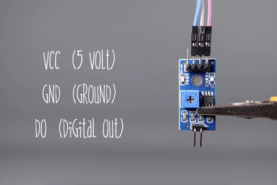
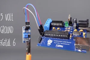
The soil moisture sensor is easy to use and only has 4 pins to connect. 3 pins were used in this project.
- DO (Digital Output) pin gives Digital output of internal comparator circuit. You can connect it to any digital pin on an Arduino. Digital 6 pin is used in the project.
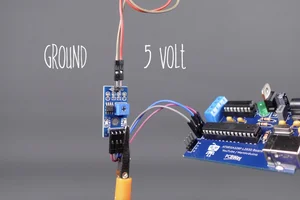
- VCC pin supplies power for the sensor. It is recommended to power the sensor with between 3.3V – 5V.
- GND is a ground connection.
- Finally, the sensor connections are completed by making the power and ground connections between the module and the probe.
Step 7: Connections - Water Pump✍️

I used the 2-in-1 board I designed myself in the project and it includes a built-in L293D motor driver. Therefore, motor connections become easier. But if you are going to use a different Arduino board and an external motor driver, the connections may be a bit more complicated. First of all, you should get basic information about "how to use" the motor driver you will use.
The built-in L293D motor output pins on the board are directly connected to the input voltage of the board and the power to the motor is controlled via the digital pins connected to the ATmega328P. The supply voltage of the board is separated for motor control and microcontroller. That is, the motor gets its power directly from the power supply and does not damage the board.
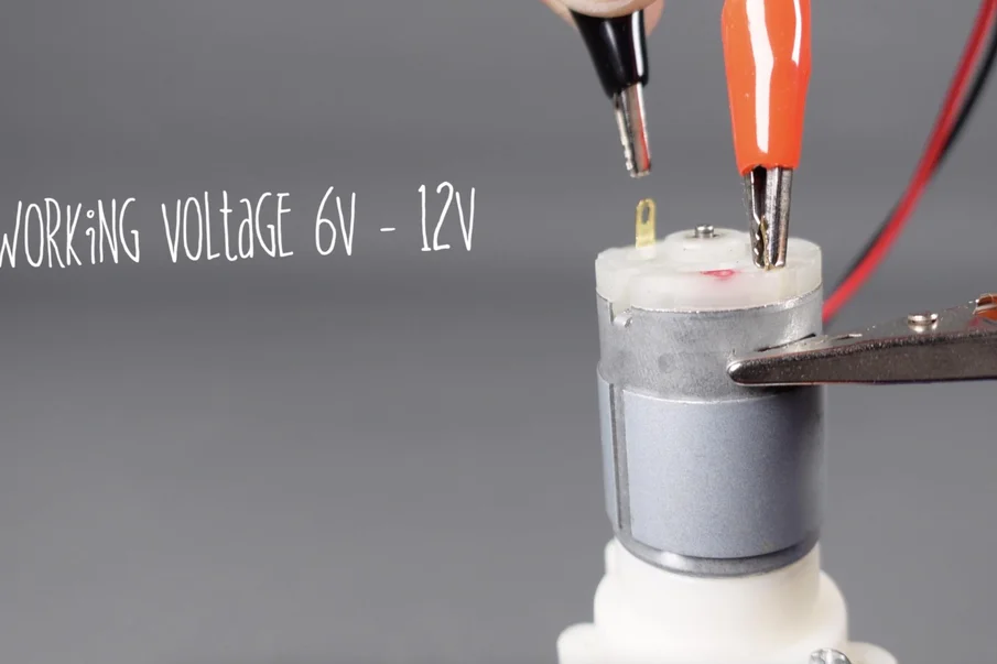
6V - 12V water pump usually has two pins:
- Negative (-) pin needs to be connected to OUTPUT1 pin of the L293D motor driver.
- Positive (+) pin (red) needs to be connected to OUTPUT2 pin of the L293D motor driver.
Power Supply Connections:
- 7.4V - 9V power supply positive (+) pin needs to be connected to VS pin of the L293D motor driver.
- 7.4V - 9V power supply negative (-) pin needs to be connected to GND pin of the L293D motor driver.
L293D motor driver and Arduino connections:
- L293D motor driver INPUT1 pin needs to be connected to Digital 2 pin of the Arduino.
- L293D motor driver INPUT2 pin needs to be connected to Digital 4 pin of the Arduino.
- L293D motor driver VSS pin needs to be connected to +5V pin of the Arduino.
Step 8: Sensing Soil Moisture✍️
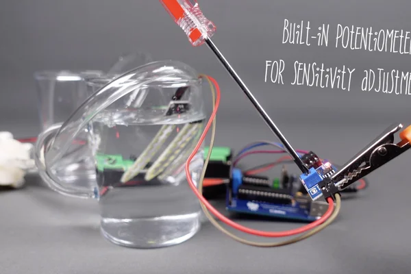
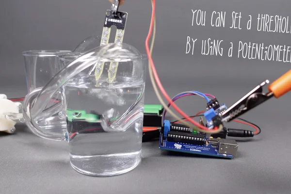
The module has a built-in potentiometer for sensitivity adjustment of the digital output (DO). You can set a threshold by using a potentiometer; So that when the moisture level exceeds the threshold value, the module will output LOW otherwise HIGH. This setup is very useful when you want to trigger an action when certain threshold is reached. For example, when the moisture level in the soil crosses a threshold, you can activate motor driver to start pumping water. Apart from this, the module has two LEDs. The Power LED will light up when the module is powered. The Status LED will light up when the digital output goes LOW.
By turning the knob of the potentiometer, you can set a threshold. So that when the moisture level exceeds the threshold value, the Status LED will light up and the module will output LOW.
Now to calibrate the sensor, insert the probe into the water when your plant is ready to be watered and adjust the pot clockwise so that the Status LED is ON and then adjust the pot back counterclockwise just until the LED goes OFF. That’s it your sensor is now calibrated and ready for use.
If you want to see this process in more detail, you can take a look at the shared project video.
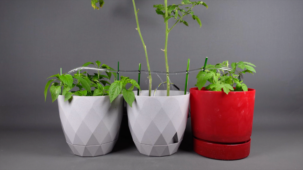
Step 9: Let's Complete the Installation!✍️


If everything is ready, let's build the automatic watering system. Of course, choose your plants for this. In this project, I decided to put 3 plants in the watering system at the same time.
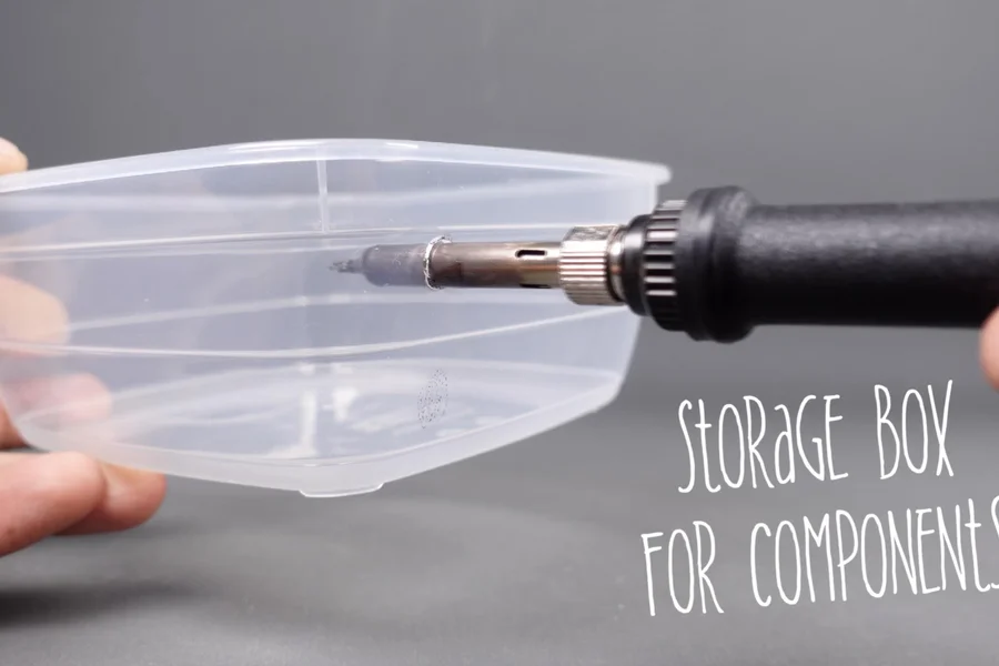
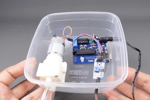
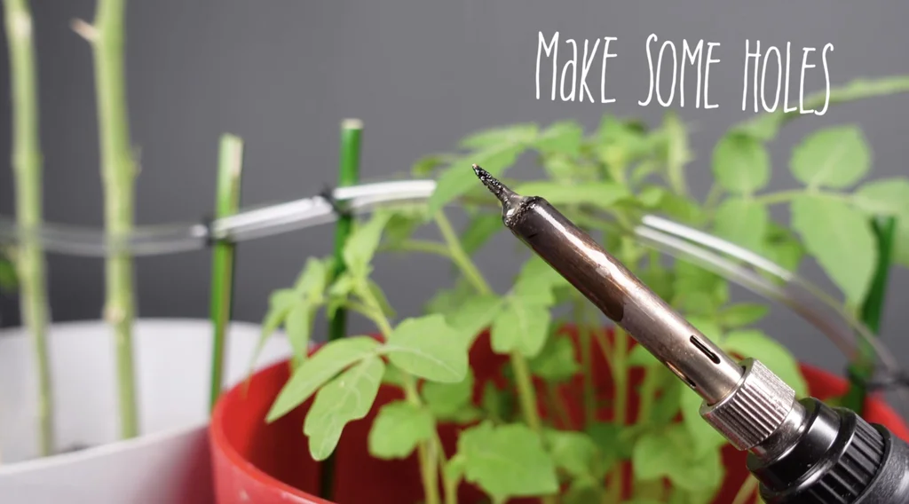
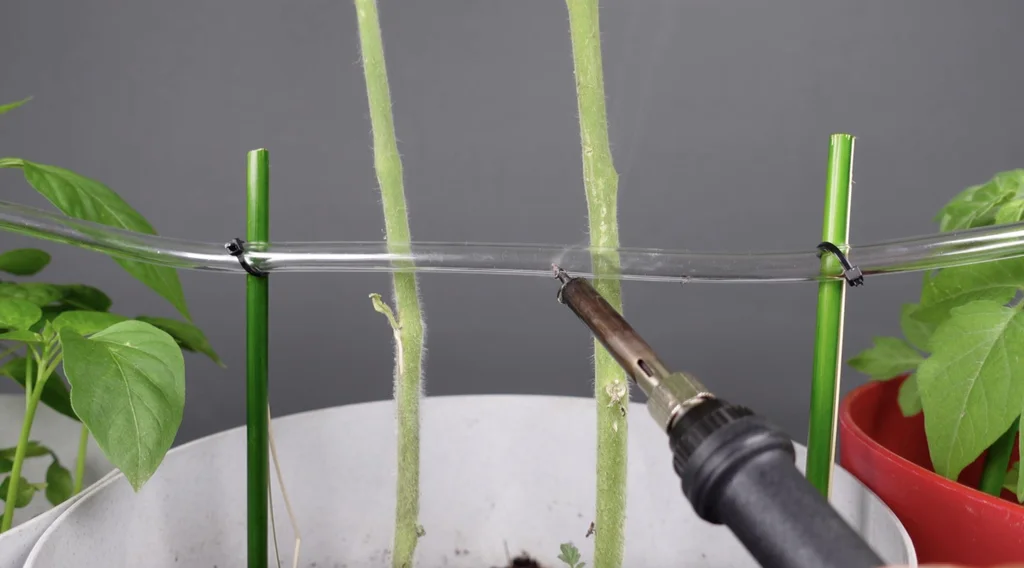
- I used a storage box to protect the electronic components from water. I made holes for the pipe and wires with an old soldering tool.
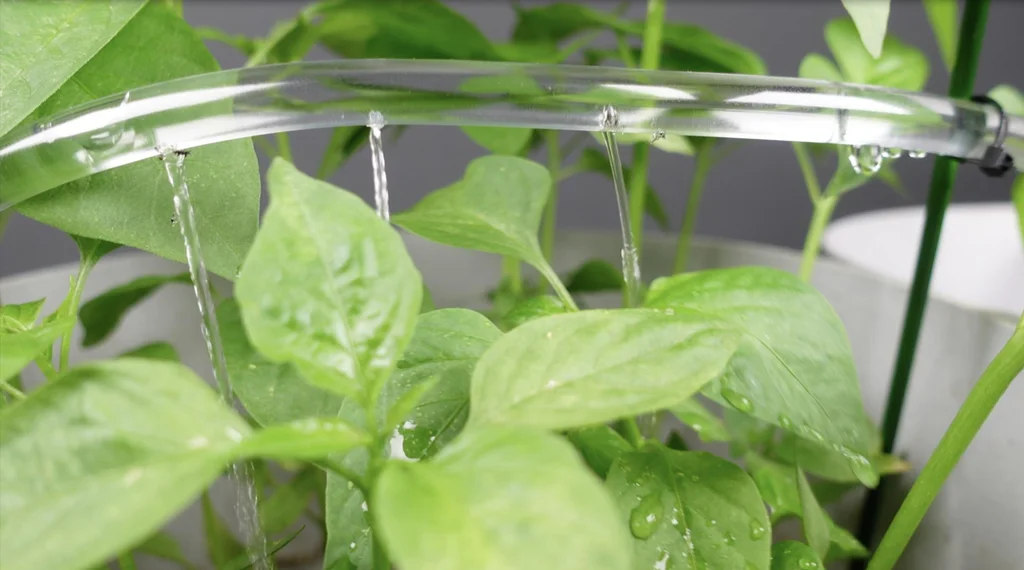
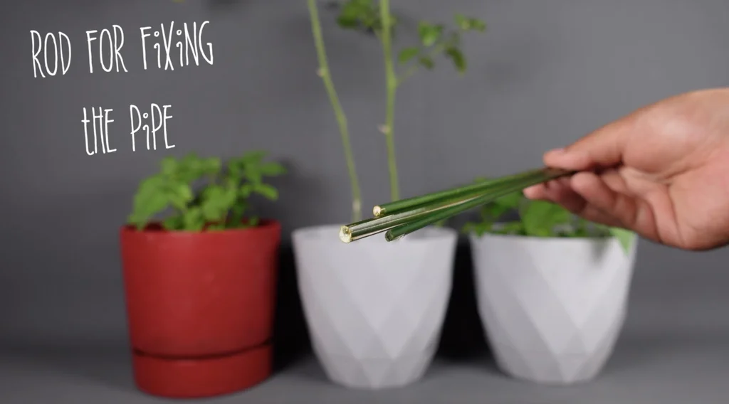
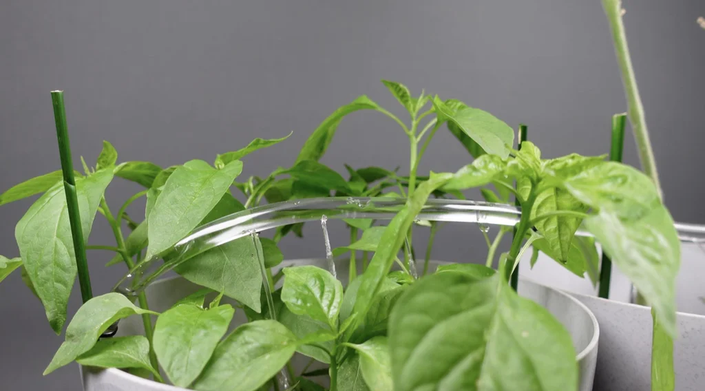
- I used some rods to fix the water pipe. I fixed the rods in the plant soil and installed the water pipe at the appropriate height to act as a sprinkler. I used a few cable ties to fixed it.
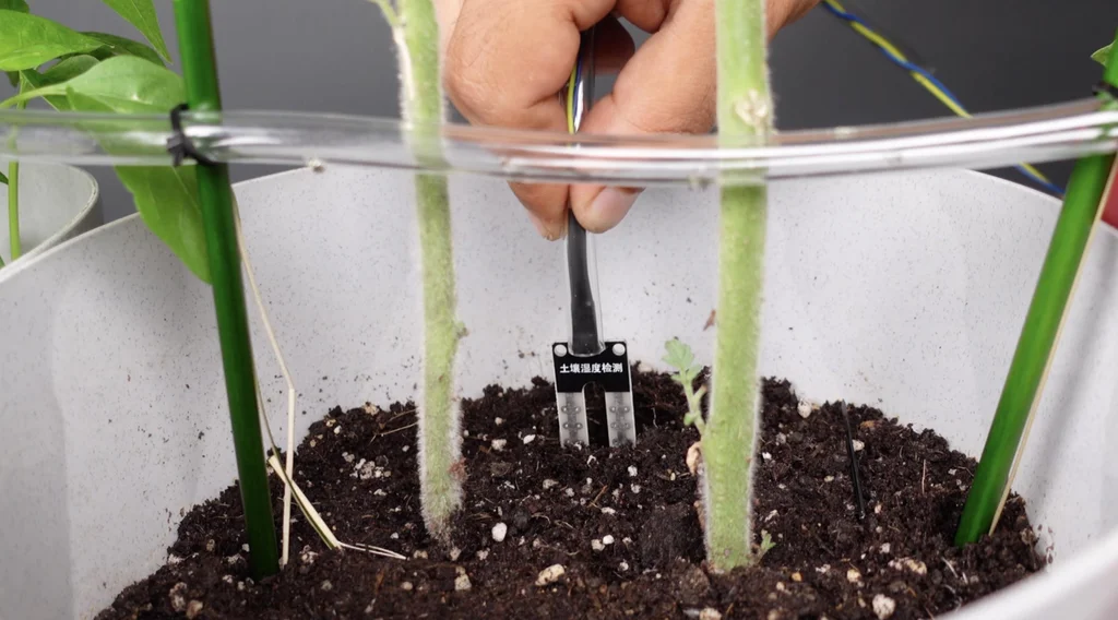
- Fix the soil moisture sensor probe in the soil. I recommend placing it away from the water pipe so that the water does not touch the probe.
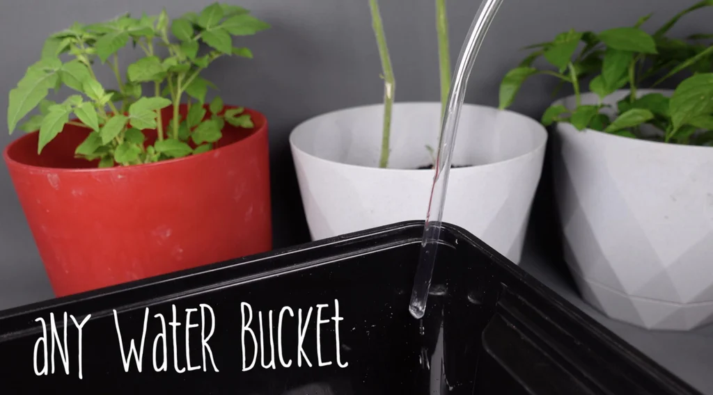
- Fix the other end of the water hose to a bucket of water and everything is ready to start the system!
Special note: The author of the above article is MertArduino , Original shared link:https://www.instructables.com/DIY-Automatic-Plant-Watering-System/??????