

My First Watering System

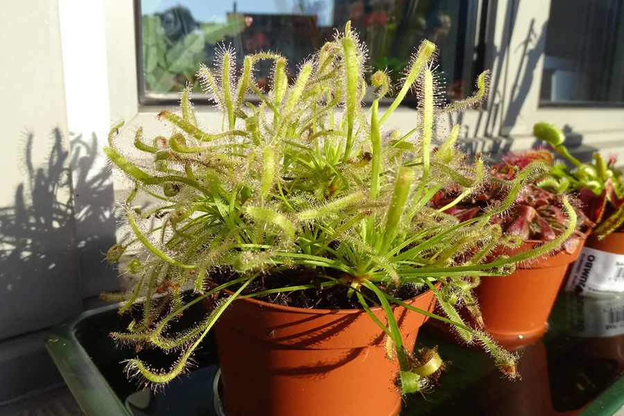

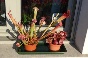
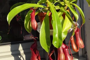
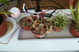
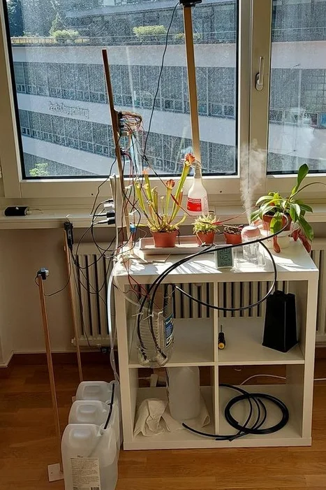
?️Recently I had to travel away from home for the period longer than a month. Just before that travel, I've purchased myself a couple of pots with carnivorous plants. It turned out that they need a lot of distilled water. Most of them prefer to stay in a bog and use tray watering method, which means simply adding water into the tray where their pots are standing. The other one, Nepenthes, is watered from the top of the pot, just like many other plants. All of them love sun and humid air.
?I had to come up with some watering system, which would have let my new plants survive, while I was traveling.
?I used to work with Arduino. I was making simple toys with buttons and LEDs. I thought that using Raspberry Pi is an overkill, and I definitely don't want to replace 2$ Arduino with ~50$ Raspberry for no practical reason. Also, I was hesitating to use pumps, because I didn't want to flood my apartment or get some electrical shortcut because of the water. But now I had to come up with the solution.
Supplies✍️
Arduino. Reads sensors. Controls water pumps.
- Arduino mini
- Capacitive soil moisture sensor
- DHT22
- LCD screen
- 3x 5V pumps
- Screw terminals
- USB power source
- 12V pump
- 12V power source
- 4x MOSFETs
- Pipes
Raspberry Pi Zero W. Controls lights and mist generator. Allows connections over ssh and provides https server.
- Raspberry Pi Zero W
- 3x optocouplers
- 3x small LEDs
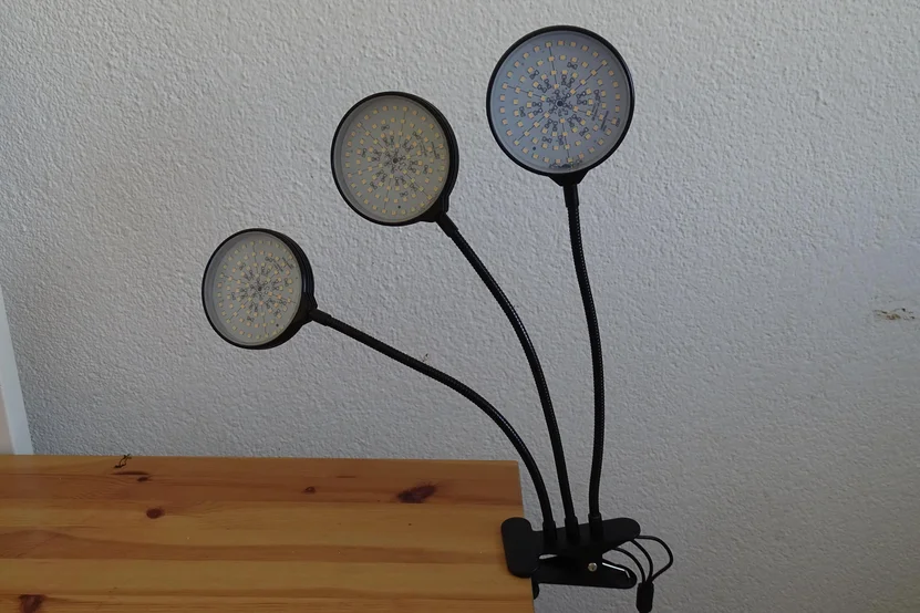
- Growing lights
- Mist maker
Raspberry Pi 3B+. Watches the garden.
- Raspberry Pi 3B+
- 3x low resolution cameras
- 1x high resolution camera
Other useful tools and components.
- Female connector rows
- Wires
- Breadboards
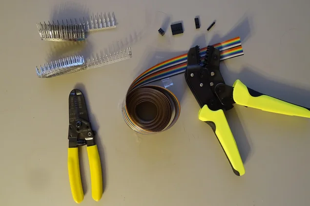
- Crimping tool
- Wire stripper tool
- Connector housings
- Male/female connector contacts
- USB chargers
Step 1: Alternatives Considered✍️
Manual system was not fitting, because I was traveling, and I just could not click the button every time when plants needed a water.
Fully automated systems could work, but I was afraid that something would go wrong. For example, if I would have a timer based system, which would turn on watering every day or twice a week, then, if the water in the tray would not evaporate fast enough, it would go over the edge and fall on the parquet. Later I discovered that this could actually happen. While I was at home, we had sunny days, and water was evaporating quite fast, but when I was traveling - the weather was cold and rainy. The water was evaporating much slower. So, my timer based approach could make a mess in my apartment.
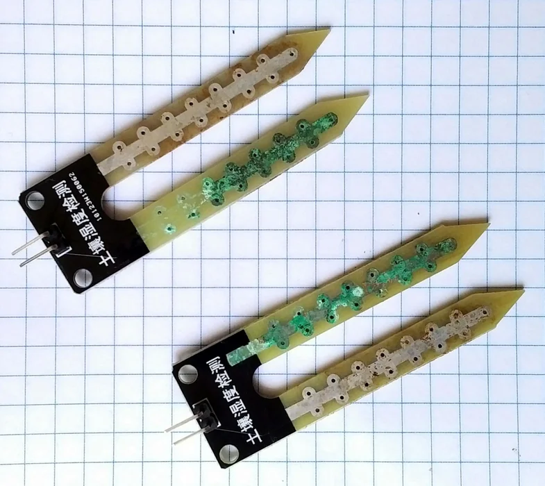
Another approach could be based on measuring soil moisture. When the soil is not moist enough - just trigger a watering. Few years ago I was using resistance based soil moisture sensors. It turned out, that if you constantly keep such a sensor under power, electrolysis happens, and one of the metal "legs" of the sensor get dissolved in the soil, which makes it poisonous not only for the carnivorous plants, but for others as well. That is why i decided to use capacitive soil moisture sensors. Naive usage would be to come up with the threshold, after which watering should trigger. In reality it turned out, that measurements of the senor depend not only on the moisture of the soil, but also on the temperature and a humidity of the air. Coming up with formulas which would estimate the real level of the soil moisture could be an interesting project involving some math and statistics.
Another problem was a resolution of the measurements. While expensive sensors were giving values between 460 (wet soil) and 520 (dry soil), cheaper ones were capable of giving something between 236 (wet soil) and 253 (dry soil). As mentioned above, fluctuations in temperature were adding even more uncertainty:
- At 7:00, temperature = 23C, soil moisture = 238
- At 11:00, temperature = 29C, soil moisture = 246
- At 19:00, temperature = 25C, soil moisture = 241
That is why, fully automated system based on measurements of the soil moisture sensor was not so attractive too.
Step 2: Final Design✍️
I wanted to get semi-automated system, where I could get all the readings from the sensors, but turn on watering only when I was absolutely sure it is safe and required.
Similar to Arduino there are some cheaper boards which are capable of serving simple http server or making http requests. But I wanted something more flexible. Ssh is the best interface I know. The simplest board known to me capable of giving me ssh access was Raspberry Pi Zero W. So, this board should be responsible for gathering measurements, and controlling pumps. And a mist maker and growing lights.
On the other hand, I wanted to see what is happening. To make sure that control circuitry will not block my watching system, I decided to use another Raspberry Pi (slightly more powerful) to capture video of what is going on. This should have being an independent controller, able to report what is actually happening.
In case of emergency, I wanted to be able to cut the power for the pumps. There is a simple and, hopefully, reliable solution - a WiFi power socket. I've added it to the system to make sure that I could stop everything through an independent interface. Having watch system based on the other Raspberry allowed me to keep it on the separate power line, so that I could keep watching surroundings after I cut the power.
These were the three main parts of the system:
- Control system, capable of gathering sensor information and controlling pumps
- Watch system, capable of visual reporting of surroundings.
- Emergency, third party cut off of the control system.
Step 3: Core. Watering✍️

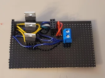
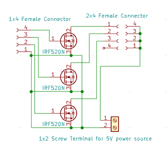
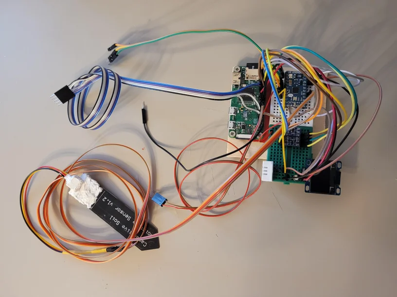
I've started from the part which I knew worst - working with pumps. It is possible to drive the pump by directly connecting it to the digital output pins of Raspberry Pi or Arduino. But they provide not so much power, and also, it is usually shared between all the pins. So, if I try to work with more than one sensor or an actuator (pump or screen), then the power is lower for each of them. That is why I decided to use the trick described in the Arduino starter projects - using MOSFET to let logical pin from Raspberry to control higher power connection for the pump. As I learned from this experiment - MOSFET cannot be easily controlled from the Raspberry Pi board, because MOSFET is triggered only when ~5V is applied to it's gate pin, while Raspberry Pi has only 3.3V on it's logical pins. So I had to use Arduino to control pumps. Using 3 MOSFETs, bunch of wires and connectors, I was able to build first driver for three cheaper pumps. It uses external 5V USB charger as power supply for the pumps.
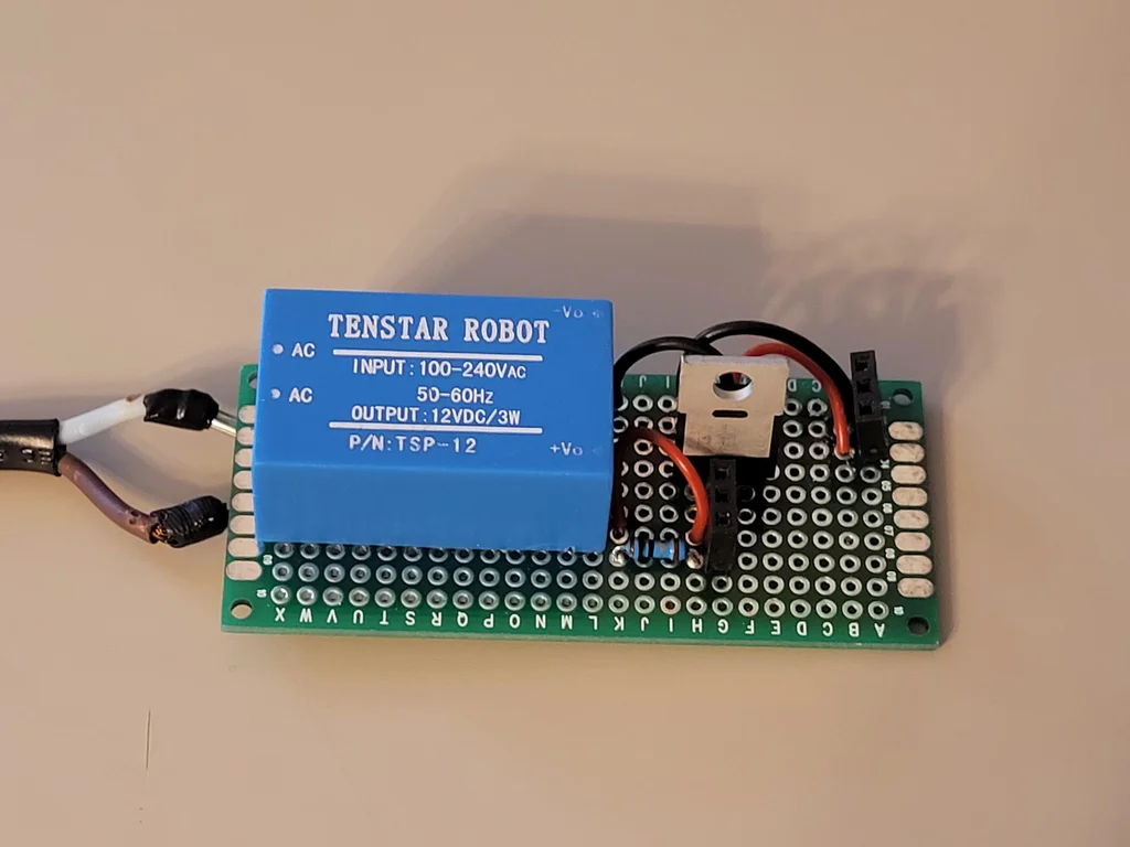
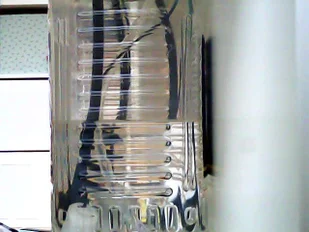
After some experimentation, it turned out, that cheaper pumps were able to lift the water higher than 60cm. I wanted plants to get as much sun as possible, so I wanted to keep them on the level of the windowsill. Also I wanted to have 3 buckets of distilled water, 5 liters each, as a supply. I could not fit them close enough to the plants, so I had to have an intermediate vessel above the main supply, and below the plants to be able to use cheaper pumps.
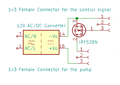
That is why I had to construct one more driver with 12V power supply and one more MOSFET.
Arduino was able to receive commands from the Serial port, turn on and off pumps, and report it's status back through the Serial port. Example of a command: "pump 2 5" where pump was a command to turn on a pump taking two parameters: first one (2 in this example) was an id 1..4 indicating pump which should be triggered; second parameter was a duration in seconds, during which pump should have been turned on. This duration is limited to values 1 to 15, so any pump was not turned on for the period longer than 15 seconds. To fully fill the tray, I usually had to trigger corresponding pump twice for 15 seconds.
Step 4: Core. Sensors✍️
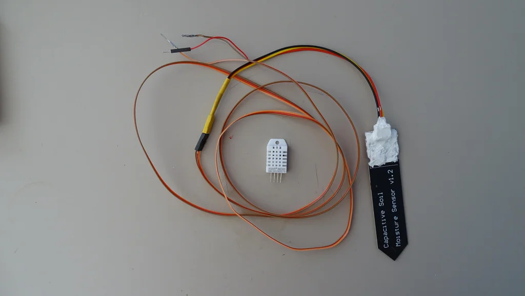
I wanted to monitor conditions around my plants, and for this I used simple DHT-22 sensor to collect temperature and humidity measurements. I also used capacitive soil moisture sensor to check if Nepenthes has enough water. For the tray I did not want to use any kind of invasive sensor to avoid adding any amount of metals into the distilled water.
Arduino was able to collect measurements from these sensors and report their values in response to the command "stats" using Serial port. Example output:
moist: 240
hum: 58
temp: 26.5
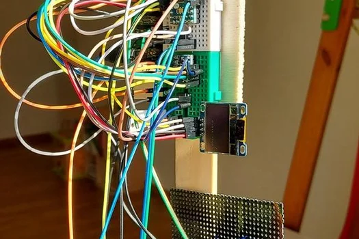
Step 5: Core. Lights and Mist Maker✍️
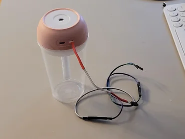
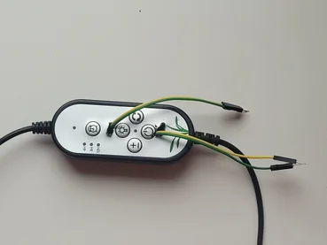
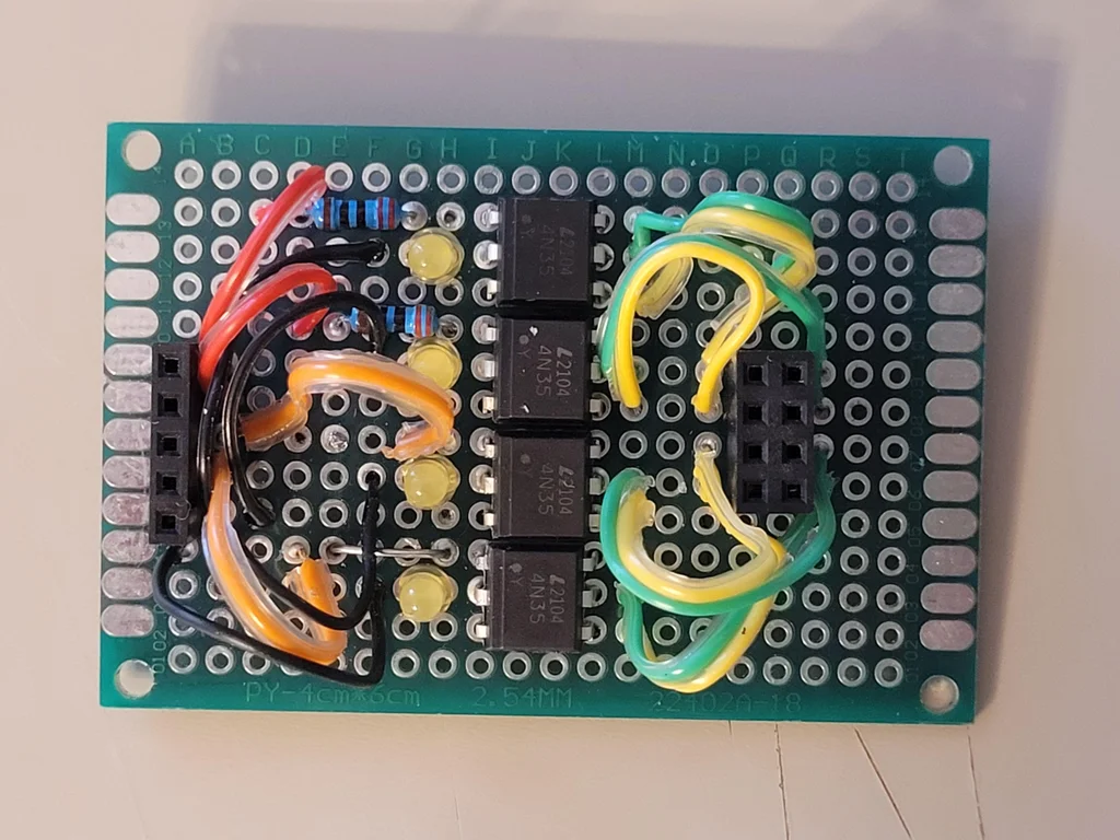
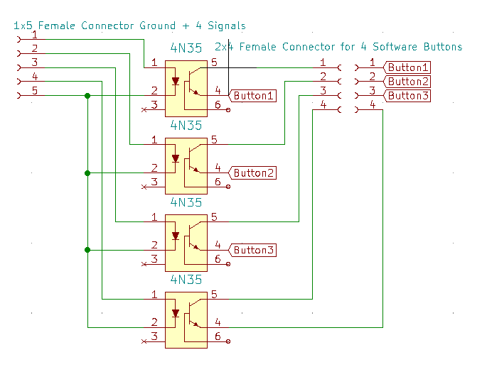
Light and mist maker were controlled by simple hardware push buttons. According to another lesson from the Arduino starters book, it is possible to programmatically "click" these buttons using optocouplers. This was the last lesson in the book and I have never had a chance to try it out. I didn't want to break any of my home electronics just to try out that lesson. Now, when I've purposely bought lights and mist maker for my automated bog garden, I finally had a chance to hack hardware buttons. Unlike MOSFETs, optocouplers can work with 3.3V signals, so they could be controlled directly from the Raspberry Pi Zero W.
Using four optocouplers, four small LEDs and a bunch of wires and connectors I was able to build a 4-software-button driver, which can be operated from the Raspberry Pi. LEDs are optional, I used them to make sure that the signal from the Raspberry Pi actually reaches the driver board.
To "click" buttons from Raspberry Pi Zero W we can use such a code:
from gpiozero import LED
from time import sleep

button = LED(17)

button.on()
sleep(0.150)
button.off()
Sleep period could be adjusted. Longer sleep period can mean long button press in some appliances.
Step 6: Core. Watch System✍️
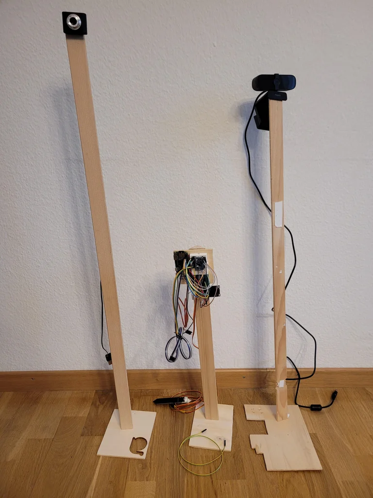

Raspberry Pi 3B+ has 4 big USB connectors. These can be used to plug web cameras. I've purchased 3 small cheap video cameras, which turned out to be quite bad. But they were fine to check small things like water level in the main water tank or in the mist maker cup. I've also purchased one better webcam capable of making HD video. It's not an amazing image quality, but much better than the cheap video cameras were making, and good enough to see how are plants doing overall.
To actually work with the video, it is possible to use ffmpeg-server tool, or separate RED5 rtmp server. I tried both, but it seems that Raspberry Pi is not capable of transcoding HD video on the fly, so I've got 5 fps video at best. Also, I was unable to reach shorter than 15sec delay of the "live" stream. Both these facts pushed me towards another solution.
I decided that a simple HTTPS server, able to enumerate video devices on the Raspberry Pi, and deliver single frame from selected video device, would be enough. For example, simple routine of adding water to the plants tray would look like this:
- Take a photo of the tray and main water tank. Visually make sure that there is not enough water in the tray, and that there is enough water in the main tank.
- Request tray pump to work for 15 seconds.
- Take another round of photos, to make sure that the water was successfully added to the tray.
- In case if there is not enough water in the main tank - add water from the water supply to the tank, before refilling the tray.
To place cameras in good positions, I've used sticks from local building market mounted to the rectangular pieces of wood serving as base. I've used self-tapping screws to couple stick and wooden base together. One good lesson to learn about using self-tapping screws is that you should make a hole before screwing the screws. Otherwise, stick can give a crack.
Later I discovered that it is possible to use ESP32-CAM device which provides quite good live video streaming. I haven't yet tried to use it for actual projects, but it seems to be a promising direction.
To take photos from connected USB cameras I used this ffmpeg command:
ffmpeg -i /dev/video0 -vframes 1 photo.jpg
All the cameras were available under even ids as /dev/video{0,2,4,6}.
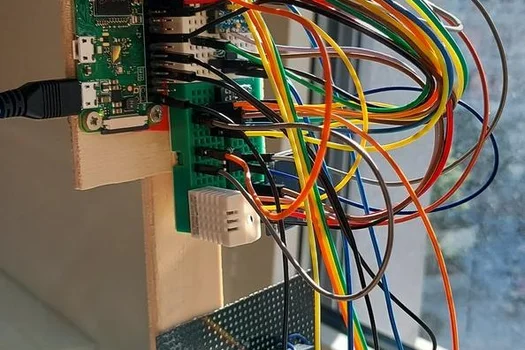
Step 7: Communication. Connecting Raspberry Pi and Arduino Using UART✍️
During my travel I could access Raspberry Pi through ssh or using https. Data about surrounding conditions and pump control was based on Arduino. To be able to communicate with Arduino from Raspberry Pi, I decided to use Serial port.
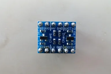
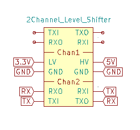
Both Arduino and Raspberry Pi are able to communicate using other protocols - SPI and I2C. But they operate on different voltages - 5V and 3.3V. It turned out that simple level shifter, which I've used for UART protocol, does not work for the I2C. There are special I2C level converters which support I2C.
Make sure that you connect TX from both boards to the pins identified as RXI or TXI (probably trailing "I" stands for Input), and RX to the RXO or TXO (same, probably trailing "O" stands for Output).
Arduino
From the Arduino side, everything is simple:
void setup() {
  Serial.begin(9600); // To initialize communication
}
void loop() {
  if(Serial.available()) {
    String command = Serial.readStringUntil("\n"); // To read an incoming command
    Serial.println("OK"); // Respond with "OK\n" as soon as possible, to notify
                          // sender that the command is received.
    Serial.print("your command was: ");
    Serial.println(command); // Echo command back.
    Serial.println("DONE\n"); // Respond with "DONE\n" on a separate line to notify
                              // sender that the command execution is complete, and
                              // Arduino is ready to receive new commands.
  }
  delay(100);
}
Here we use three very nice functions provided by the Serial library:
- Serial.readStringUntil("\n") allows us to have a protocol, which splits stream of bytes into commands by the end of line symbol. Such a protocol could be easily tested from Arduino Monitor tool (Ctrl+M in the Arduino IDE).
- Serial.print(string) sends string to the other side, but does not finish it with the "\n" symbol. This allows us to send multiple pieces of response as soon as they are ready.
- Serial.println(string) finishes sending of the single line of data.
Before connecting Arduino to Raspberry Pi, make sure that you don't have another Serial protocol client through the USB. For example, avoid powering Arduino directly from your computer though USB port. On the other hand, you can power it from the 5V USB charger. In my case, I was powering Arduino directly from Raspberry Pi, which in turn was connected to the simple USB charger.
Raspberry Pi
Serial interface is disabled on the Raspberry Pi by default. use raspi-config tool to enable it under "Interfaces > Serial Port". It asks two questions:
- if login should be enabled through the serial port - NO
- if Serial port should be enabled - YES
Now, after connecting Arduino to the Raspberry Pi, it is possible to send commands to the Arduino and receive responses:
import serial

ser = serial.Serial("/dev/serial0", 9600, timeout = 2.0) # Initialize connection
ser.write("command with parameters\n".encode()) # send a command

response = ser.read_until("\n".encode()) # Arduino should respond with OK as soon
                                         # as possible
if(response == b"OK\r\n": # In case if we got an expected OK, we can read the response
    echo = ser.read_until("\n".encode()) # should be echo of our command
    done = ser.read_until("\n".encode()) # should be DONE
In my project it was important that no USB was used to power and connect Arduino.
Protocol details
All incoming commands were one liners ending with "\n". Command name and it's parameters were separated by spaces. Example: "pump 2 15\n" command name is "pump", parameters are "2" and "15".
Arduino always responded with "OK\r\n" as soon as possible after receiving a new command. Then it could output results of the command invocation. Arduino can signal about the command finished invocation by sending "DONE\r\n" to the Raspberry Pi.
Step 8: Optional. Custom Wires✍️
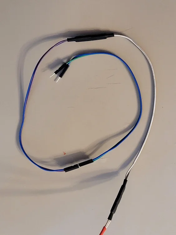
While prototyping I used to have all the sensors and micro controllers close to each other. In this case 20cm prototyping wires were working pretty well. But with the real gardening project, i turned out that actuators and sensors were located much further. In the beginning I was just connecting chains of these shorter wires to have longer one. But usually I was loosing color coding advantage, because I just haven't had so many wires of red/black color for the power and green/white/blue/yellow wires for different signals.
Later I've purchased a long rainbow stack of wires, and started to cut a wire of required length and color when I needed it. Another useful thing was a crimping tool, which allowed me to make my own prototyping wires. This allowed me to assemble and reassemble my system whenever I wanted, or move different parts around the table. This did not require me to solder or resolder connections.
Step 9: Optional. Discord Bot✍️
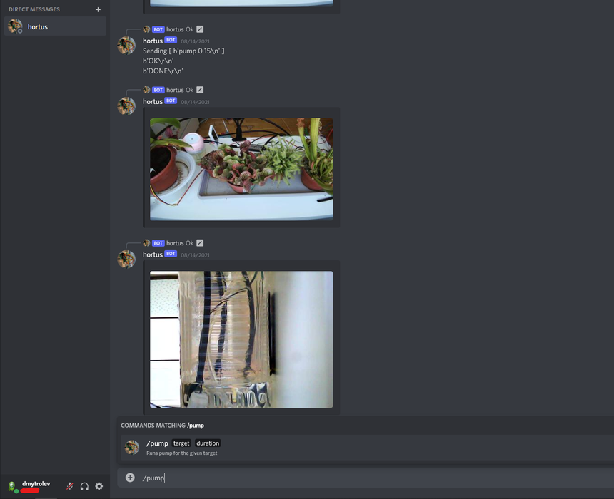
After some period of working remotely with my garden over ssh and https, I thought that it would be great to talk to it. Using some chat application like discord would allow me get photos and text messages in series, and not just as a single view of a picture or status page. It also would allow me to keep record of what was happening in the system in particular time. And finally, bot could ping me whenever it would decide that the garden needs my attention.
Step 10: Optional: Grafana✍️
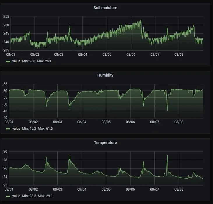
Every 10 minutes I was taking measurements of the humidity, temperature and Nepenthes soil moisture level. I've written this data into a log file in a format of SQL inserts:
INSERT INTO humidity VALUES ('2021-08-02T22:13:33', 58);
INSERT INTO temperature VALUES ('2021-08-02T22:13:33', 27.5);
INSERT INTO moisture VALUES ('2021-08-02T22:13:33', 245);
This data could be later imported into some database. To plot the data, I've used Grafana. It should be possible to display two datasets with different measurement units on a shared chart, but this function was buggy for me, so I had to create three different charts.
Anyway, from this charts I learned about a correlation between soil moisture readings and temperature in the apartment. This could be important if I would decide to implement alerting system. Threshold value would depend not only on the value of the soil moisture sensor, but also on the temperature at the moment.
Step 11: Final: Putting Everything Together✍️
In the end I was able to successfully manage my bog garden remotely from another country. The only thing which broke was a mist maker. After few weeks it just stopped turning on. After I've returned home I just plugged it out of the power, and turn on back again, and everything was working as expected.
Having computer with an ssh access turned out to be a great flexible tool. Arduino in this case seems to be a separable, low cost worker. Putting any heavy logic into it seems to be less flexible overkill. It should be able to take enough parameters for any piece of work, while Raspberry could actually make decisions what should be done and how. It can also be a nice sensor information collector.
After a month away from my bog garden, I discovered that few new pitchers grew on Nepenthes and Saracenia, while Droserra became much fluffier. I had to spend some time to trim old dead leaves from Drossera, and it was looking very nice after that.
Special note: The author of the above article is dmytrolev , Original shared link:https://www.instructables.com/My-First-Watering-System/??????