

How to set the User_Setup.h file in the TFT_eSPI library of 4.3/5/7 inch ESP32 display?

4.3/5/7 inch ESP32 display does not require setting the User_Setup.h file in the TFT_eSPI library.
2023-12-1 updated:
Because when we first made the demo code, we made it based on esp32 version 2.0.3, which will cause some users who have installed the new version to have problems during compilation. Therefore, we modified the program to be compatible with the new version of esp32 package. The screens that have been modified so far include 5-inch and 7-inch screens.
Please refer to the following link for details:
Original explanation:
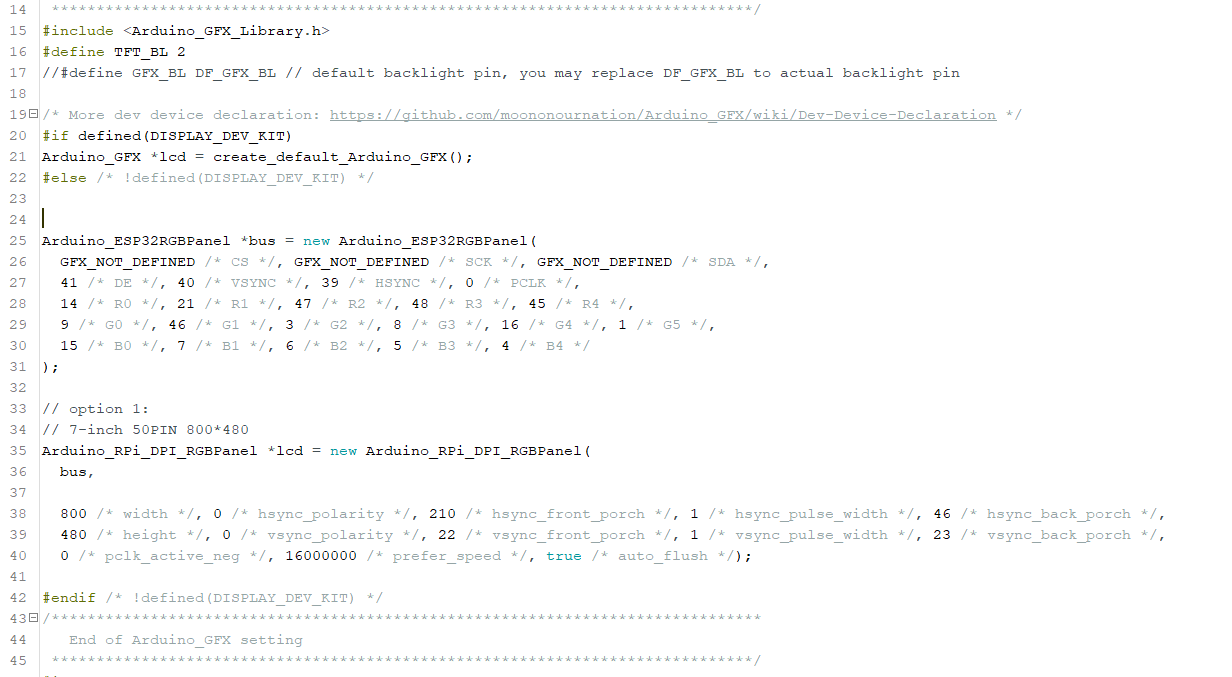
The 4.3/5/7-inch ESP32 screen is an RGB screen. We use the Arduino_GFX library as the driver. We need to define the pins and create objects according to the hardware connection of the screen. The screen setting part is in the sample program we provide, as shown in the figure(7-inch):
👉️Back to FAQ page👈️
Comments
Q: Why the pin alignment is different than the schematic?
A: Because the esp32 chip limits our RGB connection method to RGB565, that is, the screen has 3 R pins, 2 G pins and 3 B pins connected to the ground.
From the hardware schematic diagram, you can see that R0 R1 R2 is connected to ground, and R3~R7 are connected to IO14, IO21, IO47, IO48, IO45 respectively.
Therefore, when writing the code, R0 actually corresponds to R3 in the schematic diagram.
Similarly, G pins and B pins are also defined this way.
LCD Specification: